11
INSTALLATION REQUIREMENTS
• The power requirement for the system is a dedicated 20 amp circuit fitted with a circuit
breaker. This circuit may be connected to continuous or OFF peak power. Installation of
this system must be carried out only by a qualified installation technician (electrical and
plumbing).
• The surface to which the heat pump unit is installed must be firm, preferably a concrete
pad or block. If the surface is firm there is no need to fix the unit to a base surface, unless
there is a likelihood of high wind or local vibration. Appropriate fixing devices should be
used to secure both tank and heat pump unit.
• A pressure and temperature (PTR) valve is included in the installation kit of the tank unit.
This is installed in a defined point near the top of the tank unit. The PTR valve must have a
clear space where escaping steam or water can flow freely (refer AS/NZS 3500.4).
• The installation site must be well drained so that any water accumulating (such as local
rain or pipe leakage) will drain away and not enter the heat pump unit and the tank unit.
• Local water pressure must be a minimum of 200 kPa to ensure ecient functioning.
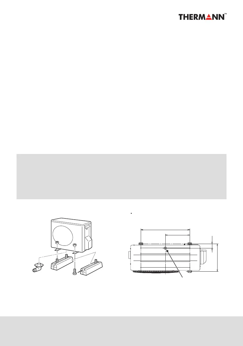
Figure 4 : Heat pump installation example and dimensions
290
Unit: mm
327.3
51
580
Heat Pump Unit
Dimensions of the legs of the heat pump unit
(overhead view)
Drain elbow
Base foundation
Supported load:
400N or more
Drain outlet
NOTE:
The entire system is set up and fully functional when supplied. Once all the water and
electric connections have been made, the system will operate automatically provided that
mains power is available. The only adjustments required is the current time setting on the
timer setting panel under the piping cover especially if the block out time setting is desired.
See current time setting and block out time section on page 16 - 18.
• Attach the drain elbow to the drain opening located on the bottom of the heat pump unit.
The drain elbow is included in the heat pump box.
• Attach a drain hose with a 16mm inner diameter to the drain elbow to guide the drained
water to an appropriate drain.
Figure: Heat pump installation example and dimensions