Form RZ-NA-I-TR, Mfg No. 121027 Rev 5,
Page 17
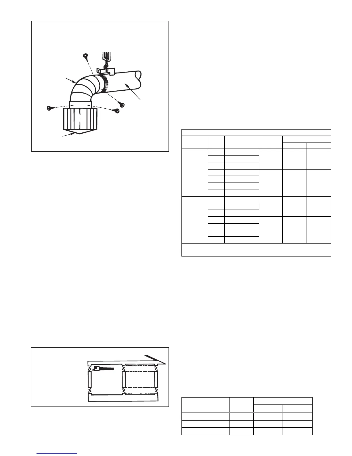
Figure 21 - Invert Terminal Cap on Indoor Vent
90°
Elbow
Vent Cap
Suspended
Tail Pipe
Attach vent cap to 90°
elbow using three non-
corrosive sheetmetal
screws spaced
approximately 120° a part.
Attach 90° elbow to tail pipe using three non-
corrosive sheetmetal screws spaced
approximately 120° a part.
13. Combustion Air
The burner is equipped with a centrifugal blower to provide combus-
tion air. The air for combustion can come either from the heated space
or be piped directly from the outside. Combustion air should be piped
from the outside if (1) the pressure in the building is negative, (2) the
atmosphere is dirt laden, (3) the atmosphere contains any substance
that will cause toxic gas when passed through a flame, or (4) the
heater is installed in a tightly closed room that does not provide re-
quired air for combustion.
If drawing combustion air from the heated space, the screened
combustion air opening on the burner box must be kept clean. Main-
tain a minimum 12" clearance from the combustion air inlet opening.
If the heater is located in a tightly closed room and is not equipped
with a combustion air inlet pipe, provision must be made to supply air
for combustion to the room.
The requirements for combustion and ventilation air depend upon
whether the unit is located in a confined or unconfined space. An
"unconfined" space is defined as a space whose volume is not less
than 50 cubic feet per 1000 BTUH of the aggregate input rating of all
appliances installed in that space. Under all conditions, enough air
must be provided to ensure there will not be a negative pressure
condition within the equipment room or space.
Do not install a unit in a confined space without providing wall open-
ings leading to and from this space. Provide adequate openings near
floor and ceiling for ventilation and air for combustion, as shown in
Figure 22, depending on combustion air source as noted below.
Add total BTUH of all appliances in the confined space and divide by
figures below for square inch free area size of each (top and bottom)
opening.
1. Air from inside building -- openings 1 square inch free area per
1000 BTUH. Never less than 100 square inches free area for each
opening. See (1) in Figure 22 above.
Confined
Space
(3)
(3)
(1)
(1) (2)
(2)
Figure 22 - Confined Space:
A space whose
volume is less
than 50 cubic
feet per 1000
BTUH of the
installed
appliance
input rating.
2. Air from outside through duct -- openings 1 square inch free area per
2000 BTUH. See (2) in Figure 22 above.
3. Air direct from outside -- openings 1 square inch free area per 4000
BTUH. See (3) in Figure 22 above.
NOTE: For further details on supplying combustion air to confined space,
see National Fuel Gas Code Z223.1 (latest edition).
If directly piped outside combustion air is required, the burner/control box
is designed to accommodate attachment of a 4" diameter inlet air pipe. For
outside combustion air, use optional inlet air kit, Option DE2. Follow the
instructions included with the kit. The inlet air pipe should be 4" diameter
pipe of a noncorroding material. The maximum length of the inlet air pipe
must not exceed the length shown in the Combustion Air Inlet Length Table
below. If the inlet air pipe passes through moisture-laden air, insulation or
double wall tubing may be needed to prevent condensation on the outside of
the pipe. Use the combustion air inlet cap supplied with the option kit. A
different type of combustion air inlet cap could cause nuisance problems
and/or unsafe operating conditions.
If the air inlet terminal is located adjacent to the exhaust terminal, the termi-
nals must be separated by a minimum distance of three feet. The only
exception is when the air inlet is located directly below the horizontal vent
cap. The required clearance between an air inlet terminal located directly
below the vent cap is 18 inches as illustrated in Figure 19B. See Figures
18B and 19B in Paragraph 12 for illustrations and clearance requirements
of an air inlet terminal located adjacent to the heater vent terminal.
14. Gas Piping and Pressures
All piping must be in accordance with requirements outlined in the National
Fuel Gas Code ANSI/Z223.1a (latest edition) or CAN/CGA-B149.1 and
B149.2, published by the Canadian Gas Association (See Paragraph 1).
Gas supply piping installation should conform with good practice and with
local codes.
Heaters for natural gas are orificed for operation with gas having a heating
value of 1000 (± 50) BTUH per cubic ft. If the gas at the installation does
not meet this specification, consult the factory for proper orificing.
The gas supply must have sufficient pressure to supply the burner plus any
other gas-fired appliances. Gas Supply pressure required at the burner
(measured with a manometer):
BTUH Gas Supply Pressure
Input Type Mini mum Maximum
50,000 - 150,000 Natural 4.5" w.c. 14" w.c.
175,000 - 200,000 Natural 6" w.c. 14" w.c.
50,000 - 150,000 Propane 11" w.c. 14" w.c.
Maximum Length of Outside Combustion Air Inlet Pipe
Type of BTUH Heater Length Maximum Equivalent Length for
Inlet Pipe Size (Straight Tubes) Length 90
o
Elbow 45
o
Elbow
50 20/25/30
c
75 20/25/30/35/40 5 ft (1.5M)
4" 100 30/35/40/45/50
Smooth 125 40/45/50
Wall 150 50/55/60
175 50/55/60/65/70
200 50/55/60/65/70
50 20/25/30
4" 75 20/25/30/35/40 N/A N/A
Corrugated 100 30/35/40/45/50
or 125 40/45/50
Flexible 150 50/55/60 N/A N/A
175 50/55/60/65/70
200 50/55/60/65/70
c
Assumes the use of three feet of flexible pipe at the combustion
air inlet on the burner/control box.
80 ft
(24.3M)
10 ft (3M)
10 ft (3M ) 5 ft (1.5M)
60 ft
(18.3M)
40 ft
(12.2M)
30 ft
(9.1M)
 Loading...