Form RZ-NA-I-TR, Mfg No. 121027 Rev 5,
Page 23
side shield is included in the installation, a screw must be inserted at each tube joint to
prevent the tubes from turning. Follow the illustrated instructions included in the side
shield package.
23. Optional Reflector Gap and End
Covers, Options CD21-27
The optional gap covers are designed to provide the infrared system with a continuous
reflector while still allowing for system expansion. The end covers are designed to
"close" the vertical space on the ends of the reflector length. Optional end covers may
only be used when gap covers are installed. Reflectors on systems with gap covers
cannot be rotated. Gap Covers are Option CD21-26; End Covers are Option CD27.
Each option kit includes illustrated instructions.
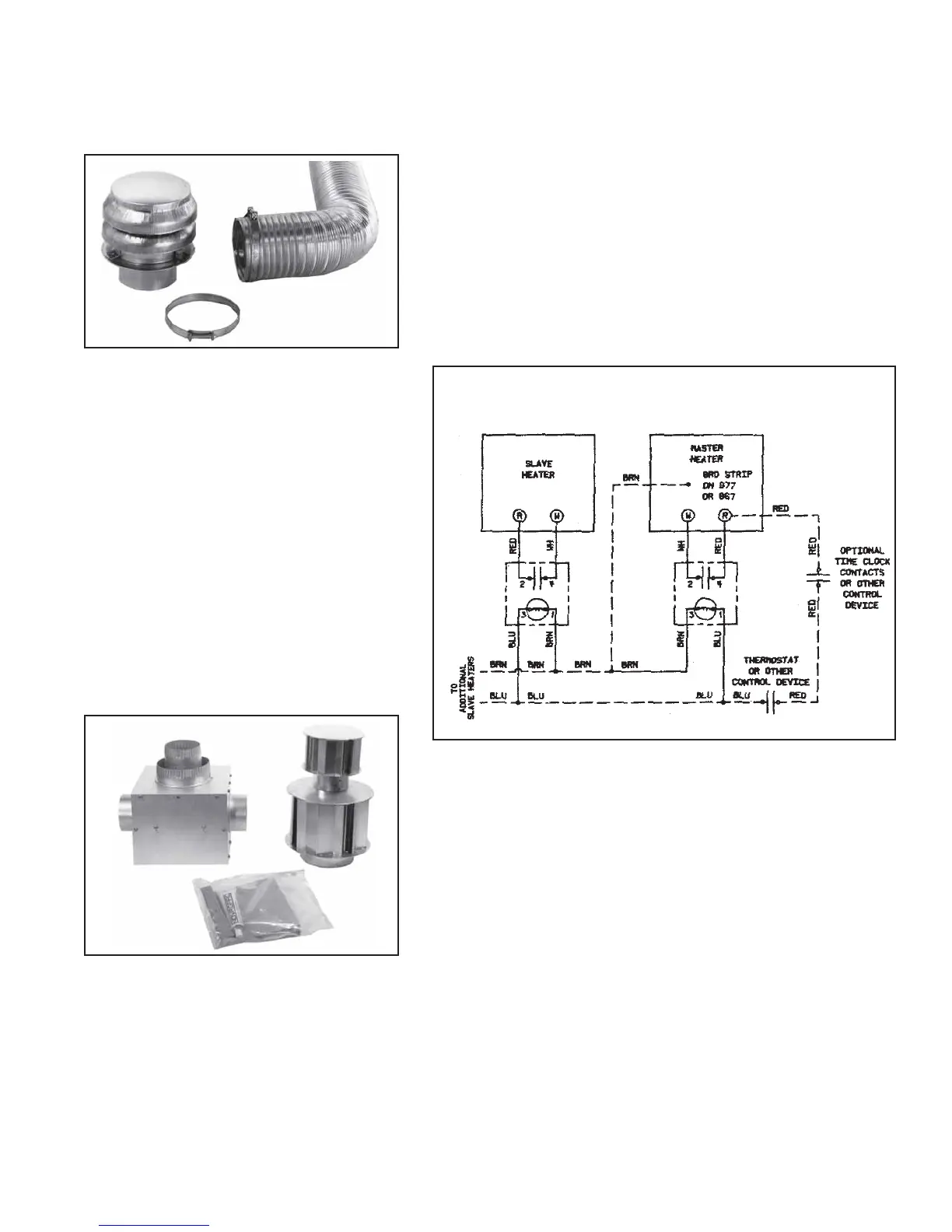
24. Multiple Heater Control, Options
CL31 and 32
These multiple heater control options permit the control of up to six heaters (one master
and five slave units) from a single thermostat or a time clock and single/multiple
thermostats. For maximum safety, the multiple control is done in the low voltage
circuit. See wiring diagram in Figure 28.
25. Optional Unit-Mounted Thermostat
Bracket Kit, Option CM3
The optional thermostat bracket kit allows attachment of the controlling thermostat to
the burner/control box. The bracket attaches at the same location as the thermostat strip
and includes a junction box for mounting the thermostat. Complete instructions are
included with the option kit. The thermostat is not included in the kit. The low voltage
thermostat may be either an optional thermostat (Option CL1) or an equivalent field-
provided thermostat.
Figure 26 -
Combustion Air Inlet
Kit, Option DE2
Figure 27 -
Dual Vent
Kit, Option
CC5
Figure 28 - Multiple Heater Control Wiring with
Option CL31 and/or CL32
combustion air inlet kit must be installed. See requirements
in Paragraph 12.
Each kit includes inlet air pipe expandable to three feet, a
terminal cap, connection hardware, and illustrated installa-
tion instructions.
21. Dual Vent Kit, Option
CC5
The dual vent option kit permits venting of two of these
heaters through only one opening in the roof or side wall of
a building. The concentric design of the vent allows each of
the two heaters to be safely operated totally independent of
the other. The two heaters may be controlled by the same or
different thermostats. Heaters vented through the optional
dual vent do not have to match in capacity, length or con-
figuration. The adapter box in the dual vent kit converts the
two separate vent pipe runs into the concentric vent termi-
nal arrangement. The specially designed dual vent adapter
box attaches indoors, close to the wall or roof opening.
Each dual vent option kit includes the adapter box, a 4"
vent cap, a 6" vent cap with concentric opening for passage
of 4" vent pipe, adapter box mounting brackets, and com-
plete instructions. Vent pipe is field supplied. Use only
single wall metal pipe.
22. Optional Side Shield,
Options CD13-20
The optional side shield hangs vertically from the reflector
brackets. Installation of the optional side shield allows for
less clearance from one side of the heater. See Paragraph 4.
The side shield is modular with two sections required per
10-ft tube. Install the two additional reflector brackets re-
quired for the side shield at the same time as the two stan-
dard reflector brackets. With a side shield attached, reflec-
tors may not be rotated more than 30
o
. When an optional