Form RZ-NA-I-TR, Page 12
3. Install the Reflector, Optional Side Shield, and Reflector
Retainers (Refer to Figure 15)
a) All Installations -- Nestle the reflector inside the flanged edges
of the reflector brackets.
b) Installations with Optional
Side Shield -- The side shield is
modular with two sections per
10-ft tube. When side shields are
included in the installation, drill a
9/64" hole in each tube joint and
insert the screw provided (See
Figure 14). Hang the side shield
sections over the ends of the re-
flector brackets (Maximum angle
with side shield is 30°). IMPOR-
TANT: Install side shield on
one side of the system only.
Figure 14 - With
optional side shield,
insert a screw in each
tube joint to prevent
tubes from turning
1/2" (13mm)
Drill
9/64"
hole
Reflector
Reflector
Retainer
U-bolt
Figure 16A -
Optional
Reflector Gap
Cover
c) All Installations -- Position a wire retainer over the reflector and hook the
ends through the holes in the reflector brackets. Install a retainer at each
reflector bracket.
d) All Installations -- Repeat the instructions to install reflectors on each
straight section of tube in the system. Do not operate the heater without all
reflectors installed.
4. Install Optional Reflector Gap Covers -- The optional gap covers are
designed to provide the infrared tubular
system with a continuous reflector while
still allowing for system expansion. If
optional reflector gap covers are included
in the installation, follow the illustrated
instructions included in the option pack-
age. Reflectors on systems with gap cov-
ers cannot be rotated.
5. Install Optional Reflector End Cover -
- The optional end covers are designed to
"close" the vertical space on both the com-
bustion chamber end and the tail pipe end
of the reflector length. The end covers may
only be installed on units that have op-
tional reflector gap covers. Follow the il-
lustrated instructions included in the op-
tion package.
6. Rotating Reflectors -- Reflectors on straight systems without reflector gap
covers or a side shield may be angled up to 45° by rotating the U-bolt and
reflector bracket.
Reflectors with gap covers cannot be rotated.
Reflectors on straight systems with a side shield may be angled up to 30°.
The side shield must hang vertically.
Figure
16B -
Optional
Reflector
End
Covers
WARNING: Do not operate heater without reflectors. See Hazard Intensity Levels, page 2.
Packaged with each straight tube is a reflector, two reflector brackets with hardware, and two reflector retainers (Refer to Figure 10E on page 7). Follow
the instructions to install a reflector on all straight tubes.
NOTE: If the installation includes an optional side shield, the side shield package (Options CD13-20) includes two additional reflector brackets and
retainers for each 10-ft tube. All four brackets must be attached to each 10-ft tube before installing the reflector.
Reflector Installation Instructions
11. Install Reflectors (including Standard Reflectors, Optional Side
Shield and Optional Reflector Gap and End Covers)
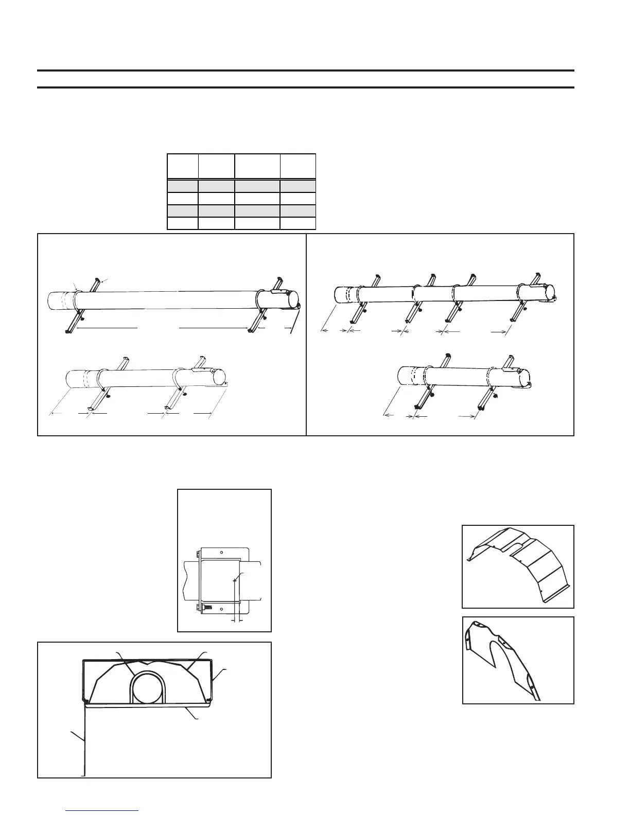
1. From the table, determine the
number of brackets (and re-
tainers) required per tube and
select the appropriate illus-
tration (Figure 13A or 13B).
2. Install Reflector Brackets
(See Figure 13A or 13B)
a) Slide the U-bolt over the tube at the determined location.
b) Position the reflector bracket as illustrated (end flanges extend-
ing upward) and slide the bracket over the bolt ends. Adjust the
bracket to the desired reflector angle (0-45
o
). Use the nuts to
attach the reflector bracket to the U-bolt.
c) Repeat the procedure to install all required brackets.
Tube
Length
Side
Shield
Number of
Brackets
Refer to
Figure
10-ft Without 2 13A
10-ft With 4 13B
5-ft Without 2 13A
5-ft With 2 13B
Figure 13A - Locations for Reflector Brackets for
Systems without an Optional Side Shield
Figure 13B - Locations for Reflector Brackets for Systems
with an Optional Side Shield
Optional
Side
Shield
Reflector
Bracket
Figure 15 - Install Reflector,
Side Shield (Optional), and
Reflector Retainers
12
(305mm)
36 (914mm)
12
(305mm)
Optional 5-ft Heat Exchanger Tube
6 feet (1.8M)
2 ft
(610mm)
approximate
Reflector Bracket
U-Bolt
10-ft Heat Exchanger Tube
10-ft Heat Exchanger Tube
Optional
5-ft Heat
Exchanger
Tube
13
(330mm)
13
(330mm)
32-3/4
(832mm)
32-3/4
(832mm)
24-1/2
(622mm)
32-3/4
(832mm)
 Loading...