Form RZ-NA-I-TR, Page 8
10. Install the Heat Exchanger Tube(s), Tail Pipe Tube, and Turbulator
Strip
There are very important steps that must be followed to suspend and assemble these tubular radiant heaters. Preparing the heater, suspension, and filed
assembly are the responsibility of the installer. Follow all instructions carefully. Throughout the instructions, continued reference to the installation
configuration drawing is required.
1) Identify the Heat Exchanger and Tail Pipe Tubes and the Parts Packaged with them (Refer to the illustrations in Figures 10A-10E and
the configuration drawing in the configuration booklet):
Connect each tube as it is suspended. If your configuration requires a
turbulator strip before a "U" or "L" tube, insert the turbulator strip before
the "U" or "L" tube is connected. Follow the instructions in Step No. 3)
on pages 9-11, and install two sections of turbulator strip. (This will only
2) Suspend and Connect the Heat Exchanger Tubes and Tail Pipe
-- Follow the Configuration Drawing Layout
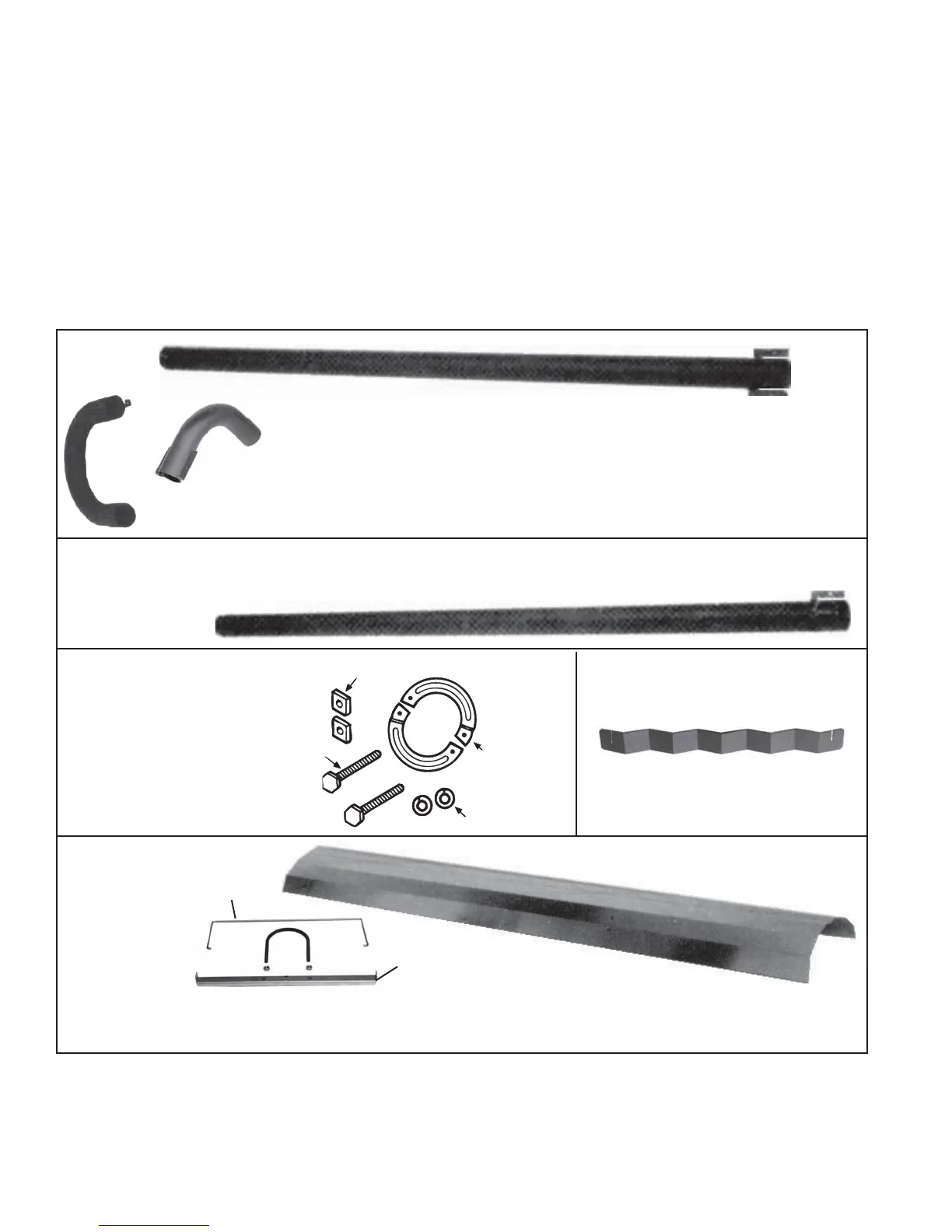
A parts bag is supplied with each
heater tube and tail pipe. The bag
contains hardware needed to
connect two tubes, an "S" hook,
and an instruction sheet.
Figure 10C -
Connection
Hardware Parts Bag,
P/N 116017
Figure 10D - One Section of the
Field-Installed Turbulator Strip
Figure 10E -
Reflector,
Reflector
Retainer, and
Reflector
Bracket and
Hardware (U-
bolt and nuts)
Reflector
Retainer
Bracket
One 10' reflector and two reflector retainers and two brackets with hardware per 10' straight tube.
Optional 5' heat exchanger tube includes a 5' reflector and two sets of retainers and brackets with hardware.
Follow installation instructions in Paragraph 11.
Figure 10A - Heat Exchanger
Tubes (Straight, "U", and "L")
"U"
Tube
"U" and "L" tube packages include
field-assembled reflectors
Expanded
End
Two Hanger
Brackets
10' Straight Tube
5' Straight Tube
Figure 10B - Tail Pipe Tube (10')
Expanded
End
Swedged End with One
Hanger Bracket
"L" Tube
Clamping
Rings
Lock
Washers
Square
Nuts
Bolts
9. Install Burner/Control Box and Combustion Chamber Tube (cont'd)
3. Suspend the Combustion Chamber Tube/Burner Box Assembly (cont'd)
recommended for use in leveling the heater. If turnbuckles are included in heater suspension, use only optional turnbuckles or field-supplied
turnbuckles of steel or malleable iron.
4. Draw Bolts -- There are two 4-1/2" long bolts left in the hardware bag. These bolts are provided as an aid in connecting tubes. Keep the bolts and
follow the tube connection instructions in Paragraph 10.
occur when installing a 40' to 70' system in a configuration where a "U"
or "L" tube connects directly to the tail pipe.)
Suspending Straight (5-ft or 10-ft) Heat Exchanger Tubes and
"U" Tubes - Attach an "S" hook to the hanger bracket and suspend the
tube from the next hanging chain. Slide the expanded end over the previ-
ous tube and make the connection.