Form RZ-NA-I-TR, Mfg No. 121027 Rev 5,
Page 3
BTUH/Length/Configurations
Depending on the length and size of the heater, the heat exchanger
sections may be installed in various configurations. Optional "L"-
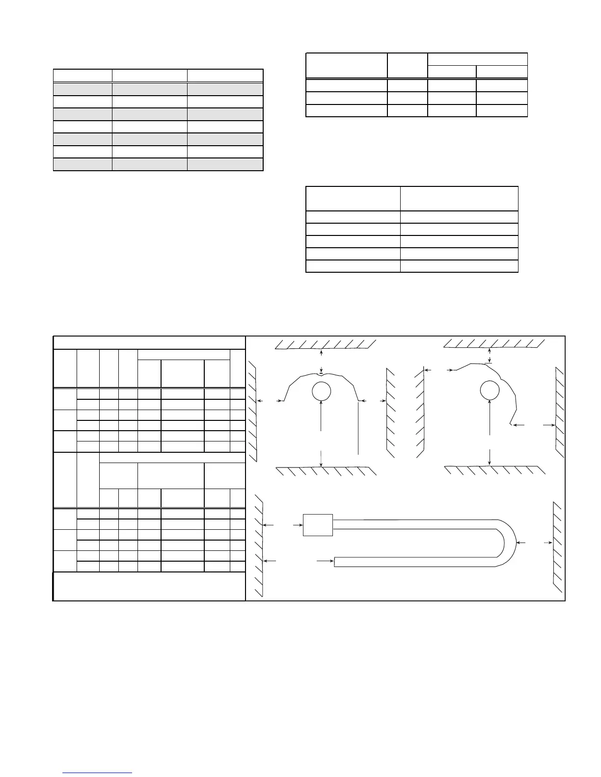
4. Clearances to Combustibles
Required clearances depend on the size of the heater (BTUH input), the position of the reflector, and the addition of an optional side shield on the rear
side of the heater. Refer to illustrations in Figure 1 to define clearances.
BTUH Input Minimum Length Maximum Length
50,000 20 feet 30 feet
75,000 20 feet 40 feet
100,000 30 feet 50 feet
125,000 40 feet 50 feet
150,000 50 feet 60 feet
175,000 50 feet 70 feet
200,000 50 feet 70 feet
BTUH Gas Supply Pressure
Input Type Minimum Maximum
50,000 - 150,000 Natural 4.5" w.c. 14" w.c.
175,000 - 200,000 Natural 6" w.c. 14" w.c.
50,000 - 150,000 Propane 11" w.c. 14" w.c.
Voltage/Phase
Standard 115/1; Optional
208/1, 230/1, 460/1
Frequency
60 Hertz
Maximum Amps
3.0
Flame Safety
Electronic
Pilot Burner Ignition
Spark
Main Burner Ignition
Pilot
shaped, 5-foot, and "U"-shaped heat exchanger tubes are available
to adapt the heaters to these configurations (Option UC2 for "L";
Option UB3 for "U"; Option UA1 for 5-foot heat exchanger tube).
Refer to the Suspension Dimensions and Configuration Drawings
Booklet (in the Owner's Envelope) to determine the permissible
configurations for each size and length of heater and guidelines for
using the 5-ft heat exchanger tube.
Gas Type and Supply Gas Pressure
Sizes 50-150 heaters are available for use with either natural or
Clearance to combustibles is defined as the minimum distance from
the heater to a surface or object that is necessary to ensure that a
surface temperature of 90°F above the surrounding ambient tem-
perature is not exceeded.
The clearances listed in the tables are installation requirements. In
addition, ANSI Z-223-1, Section 6.18, requires that signs be posted
specifying the maximum permissible stacking heights to assure that
the required clearances from the heater to combustibles are main-
tained in areas where items are stored under the heater.
Refer to Paragraph 1, Special Installations, for specific clearance
requirements for heaters installed in aircraft hangars and public ga-
rages.
5. Location and Mounting Height
When selecting the installation location, major factors to consider are (1)
Personal and Property Safety, (2) Personal Comfort, and (3) Heating Effi-
ciency
(1) Safety
The location must meet the Installation Codes listed in Paragraph 1 and any
local codes. These heaters are approved for indoor commercial/industrial
installations only. Do not install these tubular radiant heaters in areas that
contain corrosive or toxic fumes or where elements in the atmosphere could
produce corrosive or toxic fumes in the presence of an open flame. These
heaters do not qualify for explosion-proof installations.
propane gas. Sizes 175-200 are available for use with natural gas only. The
supply pressure listed is the gas pressure required at the gas valve inlet.
Measure gas pressure with a manometer.
Electrical Characteristics
Top of Reflector
Front
of
Reflector
Below the Reflector
or Below the Tube
Optional
Side
Shield
Rear
of
Reflector
Front
of
Reflector
Top of Reflector
Rear
of
Reflector
Below the Tube
HORIZONTAL REFLECTOR
REFLECTOR ANGLED (1° TO 45°)
Burner
End
Heat
Exchanger
Bend
Exhaust End
HORIZONTAL CLEARANCES
Figure 1 - Clearance Orientation
Clearances to Combustibles
Horizontal Clearances
Below
Top*
Burner
End
Heat
Exchanger
Bend (U or L)
Exhaust
End
Vent
inches
66 12 24 36 24 6
mm
1676 305 610 914 610 152
inches 78
12
30 48
24 6
mm
1981
305
762 1219
610 152
inches 84
12
30 48
24 6
mm
2134 305 762 1219 610 152
With Reflector Positioned
BTUH
Input
0-30
o
31-45
o
0-30
o
with
Side Shield
**
(000)
Front
Rear
Front Rear Front
Rear
inches
30 30 48 18 36 12
mm
762 762 1219 457 914 305
inches 42 42 66 32 42 12
mm
1067 1067 1676 813 1067 305
inches 54 54 78 36 54 12
mm
1372 1372 1981 914 1372 305
** Refer to Paragraph 10 for side shield installation.
125/
150
175/
200
BTUH
Input
(000)
* If the heater is not vented to the outside of the building, the
top clearance to combustibles is 18" (457mm).
50/75/
100
125/
150
175/
200
50/75/
100