Form RZ-NA-I-TR, Mfg No. 121027 Rev 5,
Page 5
each carton. (NOTE: Chain for hanging is not included. Use either an Optional Hanger Kit and/or Turnbuckle Kit or field-supplied hardware. See
suspension requirements in Paragraph 7.)
Accessory Cartons -- All field-installed options are shipped in separate cartons.
7. High Altitude Operation
All factory-built Model TR-H units are designed to operate at full input rates at elevations from 2001 to 6000 ft (611-1830M). In addition, Model TR-
H in Sizes 50 to 175 will operate at full rate at elevations from 2001 to 8000 ft (611-2440M).
High altitude kits are available to convert Size 50, 75, 100, 175, and 200 sea level burner/control boxes for use at high altitudes. Kits are available for
all sizes to convert from one high altitude level to another.
If the heater being installed requires high altitude conversion, contact your distributor to obtain the appropriate kit and complete the conversion as part
of the burner/control box preparation in Paragraph 9.
8. Suspension Dimensions and Preparation
Refer to the Suspension Point Dimensions and Installation Con-
figuration Drawings Booklet. This booklet provides suspension
point dimensions, illustrations of permissible configurations for
each size and length of heater, and requirements that must be met to
include an optional 5-ft heat exchanger tube in the system.
From the dimensions on the selected configuration drawing, deter-
mine the building suspension points.
WARNING: Install heaters only in the
configurations illustrated or noted in the
configuration booklet (Form RZ 607 in the
Owner's Envelope). Don't install a heater in
a configuration that is not permissible for that
BTUH input capacity or length. See
Paragraph 3 and Hazard Levels on page 2.
Suspension Point Requirements:
1) Supporting structure must have a minimum load-carrying ca-
pacity of 200 lbs. (Do not suspend the heater from gas piping
or electrical conduit.)
2) Clearances to combustibles must be observed. See Paragraph
4.
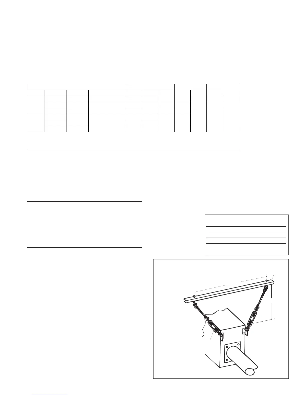
3) Heater must be suspended by hanging chains. Chain, "S" hooks,
and/or turnbuckle length at each suspension point must be a
minimum of 12 inches. All chains suspending tubes must be
plumb. See Figure 2 for dimensions for burner/control box
suspension points.
4) Refer to Paragraph 5 for recommended minimum mounting
heights. The installer is responsible for properly and adequately
fastening the chains to the building and supporting the weight of
the heater. Depending on the type of building construction at the
installation site, either attach the chain support directly to the build-
ing or attach and extend a support to the location needed.
SUPERSTRUT
®
brackets or a comparable metal strut material is
well suited as a support structure that requires numerous suspen-
sion points.
Chain must accept a 1/4" "S" hook and have a minimum of 200
lbs working load rating. Use either optional hanging chain kit
(Option CK11) or field-supplied chain.
Since the heater must be level, turnbuckles are recommended at the "S"
hook connections on the heater. Turnbuckles must be of steel or malleable
iron. Use either optional turnbuckle kits (Options CK12-20) or field-sup-
plied equivalent.
A minimum length of 12" of chain, "S" hooks and/or turnbuckle is required
at each suspension point.
Chains suspending tubes must be plumb when the heater is installed.
Suspension points required for the burner/control box are illustrated in
Figure 2.
This tubular radiant heater
must be suspended with
chain because the tubes will
expand when heated. The
overall length of a straight
system will expand ap-
proximately as shown in
the table.
Straight System Expansion Length
70 ft 2-3/4" (70mm)
60 ft 2-3/8" (60mm)
50 ft 2-1/8" (54mm)
40 ft 1-7/8" (48mm)
30 ft 1-1/2" (38mm)
20 ft 1-1/8" (29mm)
High Altitude Conversion Kits
(full rate operation)
Gas feet meters
50 75 100 125* 150* 175 200
2001-4000 610-1219 U.S. or Canada** 126440 120880 120882 132664 132667 132670 132673
4001-6000 1220-1828 U.S. Only 126442 120884 120886 132682 132685 132688 132691
6001-8000 1829-2438 U.S. Only 126444 120888 120890 132700 132703 132706 N/A
2001-4000 610-1219 U.S. or Canada** 126441 120881 120883 132676 132679 N/A N/A
4001-6000 1220-1828 U.S. Only 126443 120885 120887 132694 132697 N/A N/A
6001-8000 1829-2438 U.S. Only 126445 120889 120891 132712 132715 N/A N/A
**Canadian high altitude installations must choose kits designed for 2001-4000 ft (610-1219M) elevation.
TR/TR-H
*Kits for Sizes 125 and 150 may only be used to change a Model TR-H from one high altitude elevation to another.
DO NOT attempt to field convert a sea level Model TR125 or TR150 to high altitude.
Natural
Gas
Only
Propane
Gas
Only
TR/TR-H TR-H only
Structural support added by the
installer or part of the building structure
A + A/4
A
At least 12
(305mm) of
chain MUST
BE used for
proper expansion
movement.
Optional turnbuckle
Use for convenience
if space permits.
Figure 2 - Suspension
Dimensions and Hanging
Arrangement of the
Burner/Control Box