Form RZ-NA-I-TR, Page 16
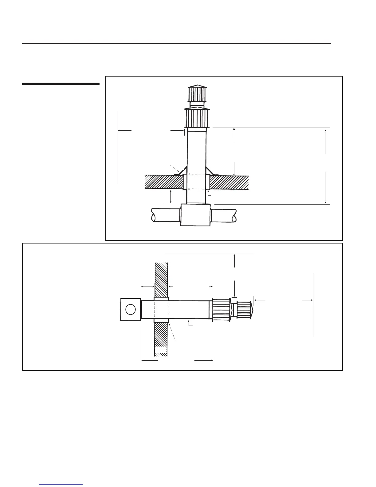
6 (152mm)
clearance to combustibles
Dual Vent
Adapter Box
Approved thimble required when the flue pipe
extends through combustible materials.
6 ft (1829mm)
maximum
6 ft (1829mm)
minimum
Vent pipe
from heater
Vent pipe
from heater
Vertical extension must be 6 (152mm)
higher than anticipated snow depth
but not less than 24 (610mm) above
the roof
Roof Flashing
Parapet or adjoining bulding
Single wall outer dual vent pipe
Single wall inner dual vent pipe
Roof or building overhang
3 ft (914mm)
minimum
6 ft (1829mm)
minimum
18 (457 mm)
minimum
6 (152mm)
clearance to combustibles
Dual Vent
Adapter Box
Wall
6 ft (1829mm)
maximum
Parapet or adjoining building
Pitch flue pipe down toward outlet 1/4 inch
per foot for condensate drainage.
Approved thimble required when the flue pipe
extends through combustible materials.
Single wall outer dual vent pipe
Single wall inner dual vent pipe
Figure 20B - Horizontal Dual Vent
Terminal Arrangement
Figure 20A - Vertical
Dual Vent Terminal
Arrangement
11. Venting (cont'd)
Vent Terminal Arrangements (cont'd)
Unvented Installation -- These tubular radiant heaters are approved for
operation without an outdoor vent. Before installing a tubular infrared
heater in the unvented mode, extreme care should be exercised in exam-
ining the building atmosphere and structure. Fresh air requirements
are 4 CFM/1000 BTUH for natural gas and 5 CFM/1000 BTUH for
propane gas.
• Do not operate in the unvented mode when dust or dirt are present.
• Do not operate in the unvented mode in a building where contami-
nants are in the air that will produce a toxic gas when burned or
exposed to high temperatures.
NOTE: If either of the above situations exist, it is recommended that
a vented system with an optional combustion air inlet be installed.
• Do not operate in the unvented mode if there is any doubt about the
quality of the insulation in the building. Unvented operation in a
building that has an uninsulated roof or that may have uninsulated
structural members partially exposed to the outdoors may result in
condensation. The condensation may be severe enough to drip and/
or cause corrosion.
• Do not install in the unvented mode with outside combustion air
unless the inlet air cap is at or below the plane of the heater.
When installing a tubular infrared heater in the unvented mode, a vent
cap must be used and must be installed inverted as illustrated in Figure
21.
When a heater is operated without being vented to the outdoors, "TOP"
clearance to combustibles changes to 18 inches (See Paragraph 4).
WARNING: Dual venting of two heaters is permitted only when using the Dual Vent Kit, Option
CC5. (Refer to Figures 20A and 20B.) No other manifolding of vent runs is permitted due to possible
back pressure and recirculation of combustion products into the building. See Hazard Levels, page
2.
Duel Venting -- By using the Dual
Vent Option Kit, Option CC5, two
heaters may use the same vent termi-
nal. No other dual venting arrange-
ment is approved.
Follow the installation instructions
and requirements included in the Op-
tion Kit. See Vent Terminal Arrange-
ments in Figures 20A and 20B.
 Loading...