Form RZ-NA-I-TR, Mfg No. 121027 Rev 5,
Page 7
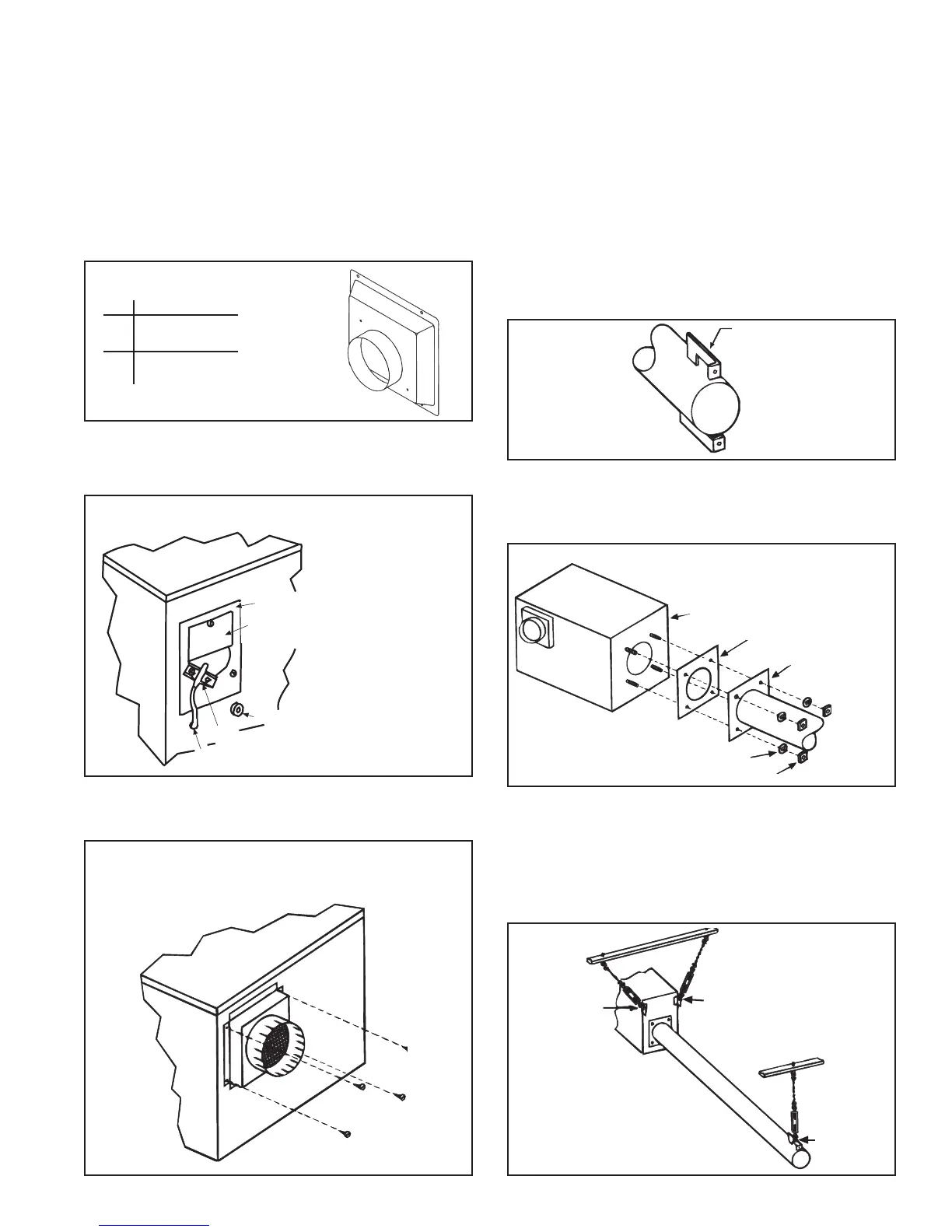
Instructions:
1. Refer to Figure 6 and identify the combustion air inlet side of the
burner box. If paper warning label is attached, remove.
2. Position the combustion air inlet cover over the air inlet opening.
Using the four screws in the parts bag, attach the cover to the burner/
control box. See Figure 7.
Figure 7 - Attach Combustion Air Inlet Cover (Field-
attachment of the combustion air inlet cover is
required with either an indoor or outdoor combustion
air supply.)
Figure 6 - Combustion Air Inlet Side of the Burner/
Control Box
Figure 5 - Combustion Air Inlet Cover
4. Adhere label(s) to the burner/control box directly below the rating
plate.
Field size conversion is complete. Continue to STEP 2) Install Com-
bustion Air Inlet Cover.
STEP 2 -- Install Combustion Air Inlet Cover -- Applies to all burner/
control boxes.
From the hardware bag in the burner/control box, remove the instruction
sheet and the parts listed in Figure 5.
STEP 3 -- Assemble and Suspend the Burner/Control Box and
Combustion Chamber Tube
Use these parts (from the hardware bag) to assemble the box and tube.
Qty Description P/N
4 Lockwashers 1333
4 Nuts 1035
1 Gasket 116029
Instructions:
1. Identify the Combustion Chamber Tube -- The tube with the
square flange welded to one end.
2. Attach Combustion Chamber Tube to Burner/Control Box --
Slide the gasket over the bolts on the burner end of the burner/control
box (See Figure 8B). Position the tube so that the hangers (on the end
of the tube) are toward the top and bottom. See Figure 8A.
Slide the flange over the bolts. See Figure 8B.
Use the washers and nuts to attach the combustion chamber flange
securely to the burner/control box. (The bolts are pre-welded to the
inside of the box.)
3. Suspend the Combustion Chamber Tube/Burner Box Assem-
bly
Parts needed from the hardware bag: 3 "S" Hooks
Attach the two "S" hooks to the hanger brackets on the burner/control
box. Attach the third to the top hanger bracket on the end of the
combustion chamber tube. Suspend the assembly from the three hang-
ing chains. Refer to Figure 9.
The illustration in Figure 9 includes turnbuckles. Turnbuckles are
Figure 8A - End
of Combustion
Chamber Tube
Showing
Position of
Hanger
Brackets
Position hanger
brackets at the top
and bottom
Burner/Control Box
Fiberglass
Gasket
Combustion
Chamber
Lock washers
5/16-16 Nuts (tighten alternately)
Figure 8B - Attach the Combustion
Chamber Tube to the Burner/Control
Box. Alternately tighten nuts.
Attach "S" Hook
Attach
"S"
Hook
Attach
"S"
Hook
Figure 9 -
Suspended Burner/
Control Box with
attached
Combustion
Chamber Tube
Combustion Air Restrictor Plate
Warning label which
must be removed
Static Pressure Port
Combustion Airflow Sensor
Tubing to Pressure Switch
IM
PO
RTANT
Qty Description
1 Combustion Air
Inlet Cover
4 Screws, #10 x
1/2" long