Form RZ-NA-I-TR, Page 6
9. Prepare and Install Burner/Control Box and Combustion Chamber
Tube
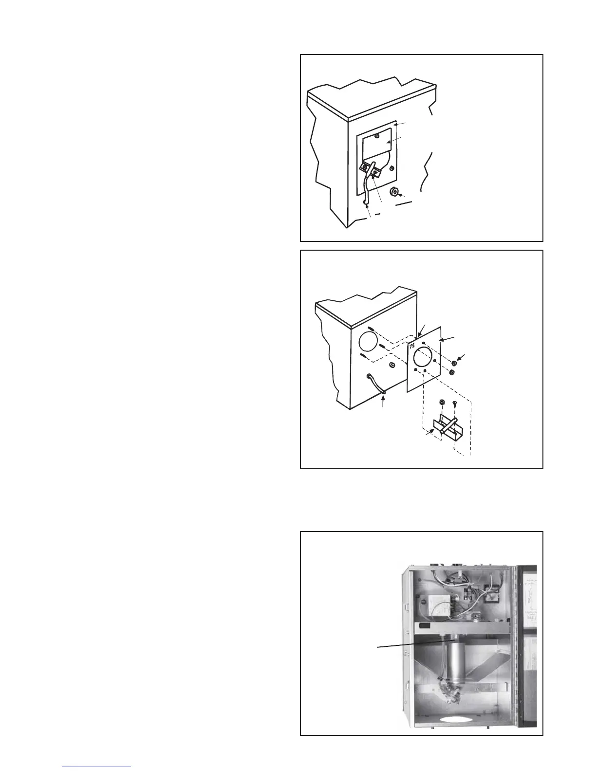
Figure 3A - Combustion Air Inlet Side of
Burner/Control Box
Figure 3B - Remove factory-installed air restrictor plate
and replace with the restrictor plate in the parts bag
Figure 4 - Burner/Control Box Showing Location of
the Burner Orifice
Burner Orifice
-- Remove with
9/16" open end
wrench
Model Size is stamped
in the upper left hand corner
Combustion Air
Restrictor Plate
10-32 Nuts
Rubber tubing (attaches to
combustion airflow sensor)
Combustion Airflow Sensor
There are very important steps that must be followed to prepare, sus-
pend, and assemble these tubular radiant heaters. Preparing the heater,
suspension, and field assembly are the responsibility of the installer.
Follow all instructions carefully.
STEP 1) Prepare Burner/Control Box
All burner/control boxes require some field preparation. The type of
preparation depends on how the unit was ordered and where it will be
installed. Determine which of these six situations matches your applica-
tion and follow the appropriate instructions. The first three are for units
ordered by specific size; the last three are for burner/control box pack-
ages that cover two sizes. (Refer to Paragraph 6 for further explanation
on packaging.)
• The unit was ordered as a specific size to be installed at a specific
elevation (sea level or high altitude) and is being installed at
that elevation. Proceed to STEP 2 of these Preparation instructions.
• The unit was ordered as a specific size to be installed at sea level
to 2000 ft and is being installed above 2000 ft (NOTE: Does not
apply to Sizes 125 and 150). Install the high altitude kit selected in
Paragraph 7. Follow the instructions provided with the kit. When the
kit is installed, proceed to STEP 2 of these Preparation Instructions.
• The unit was ordered as a specific size to be installed at an
elevation above 2000 ft and is being installed at a different eleva-
tion above 2000 ft. Install the high altitude kit selected in Paragraph
7. Follow the instructions provided with the kit. When the kit is
installed, proceed to STEP 2 of these Preparation Instructions.
• The burner/control box was ordered as a TR75/100, TR125/
150, or TR175/200 and will be installed at sea level to 2000 ft as
a Size 75, 125, or 175. Proceed to STEP 2 of these Preparation
instructions. (The Size Conversion Kit shipped with the burner/con-
trol box will not be used.)
• The burner/control box was ordered as a TR75/100 or TR175/
200 and will be installed above 2000 ft elevation as a Size 75, 100,
175, or 200. Install the high altitude kit selected in Paragraph 7.
Follow the instructions provided with the kit. When the kit is in-
stalled, proceed to STEP 2 of these Preparation Instructions. (The
Size Conversion Kit shipped with the burner/control box will not be
used.)
• The burner/control box was ordered as a TR75/100, TR125/
150, or TR 175/200 and will be installed at sea level to 2000 ft
elevation as a Size 100, 150, or 200. Follow the instructions below
to install the size conversion kit shipped with the burner/control box.
Instructions to Change the Combustion Air Restrictor Plate and
Burner Orifice to Field Convert a Burner/Control Box from Size
75,000 to 100,000; or from Size 125,000 to 150,000; or from Size
175,000 to 200,000.
Parts Required: Conversion package in the burner/control box includ-
ing a burner orifice, a combustion air restrictor plate, and conversion
labels.
1. Conversion Size Labels (one on the restrictor plate, one or two
loose) -- Fill-in all labels stating that the burner/control box has been
converted to either a Size 100,000, 150,000 or 200,000.
2. Change Air Restrictor Plate -- Refer to Figure 3A and identify the
combustion air inlet on the side of the burner box. Locate the paper
warning label on the factory-installed combustion air restrictor plate.
Attached to the restrictor plate is a combustion air sensor tube and
bracket. See Figure 3B.
Remove the hardware (screws and/or nuts) holding the combustion
air sensor bracket and the restrictor plate. Remove and discard the
factory-installed combustion air restrictor plate. Using the same hard-
ware, attach the combustion air restrictor plate shipped in the parts
bag. Re-attach the combustion air flow sensor bracket.
3. Change Burner Orifice - Open the hinged access panel on the
bottom of the burner/control box. Locate the burner orifice. See Fig-
ure 4. Using a 9/16" open-end wrench, remove and discard the fac-
tory-installed burner orifice. Install the burner orifice shipped in the
parts bag. Close the bottom panel.
Combustion Air Restrictor Plate
Warning label which
must be removed
Static Pressure Port
Combustion Airflow Sensor
Tubing to Pressure Switch
IMPORTANT