Form RZ-NA-I-TR, Mfg No. 121027 Rev 5,
Page 19
WARNING: All components of the gas supply
system must be leak-tested prior to placing
equipment in service. NEVER TEST FOR
LEAKS WITH AN OPEN FLAME. See Hazard
Levels, page 2.
Manifold or Orifice Pressure Settings
Measuring manifold gas pressure cannot be done until the heater is in
operation. It is included in the steps of the "Check-Test-Start" procedure
in Paragraph 16. The following warnings and instructions apply.
Before attempting to measure or adjust manifold gas pressure, the inlet
(supply) pressure must be within the specified range for the gas being
used both when the heater is in operation and on standby. Incorrect inlet
pressure could cause excessive manifold gas pressure immediately or at
some future time.
Instructions for Checking Manifold Pressure:
1) With the manual valve (on the combination valve) positioned to pre-
vent flow to the main burners, connect a manometer to the 1/8" pipe
outlet pressure tap in the valve. NOTE: A manometer (fluid-filled gauge)
is recommended rather than a spring type gauge due to the difficulty of
maintaining calibration of a spring type gauge.
Since the tubular heater does expand and contract, the connection be-
tween the supply line and the heater must allow for expansion and con-
traction. Use either an expansion coil (12" minimum diameter) or, if
permitted by local code, a flexible connection. If a flexible connector is
installed, use only an CSA certified, stainless steel connector with a
maximum length of 24" and a minimum size of 1/2" I.D. If a flexible
connector, Option CE3 or CE4, was ordered with the heater, it will be
shipped separately. Optional flexible connectors have the following pres-
sure drops.
WARNING: Strong cleaning solutions or
chemical substances must not come in contact with
the flexible connector.
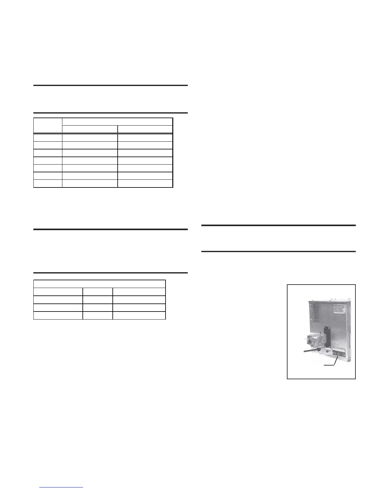
Figure 24 -
Thermostat
Connections
Terminal
Strip
Manifold Pressure Settings
BTUH Input Gas Manifold Pressure
50,000 - 150,000 Natural 3.5" w.c.
175,000 - 200,000 Natural 5" w.c.
50,000 - 150,000 Propane 10" w.c.
15. Electrical Supply and
Connections
All electrical wiring and connections, including electrical grounding
MUST be made in accordance with the National Electric Code ANSI/
NFPA No. 70 (latest edition) or, in Canada, the Canadian Electrical
Code, Part I-C.S.A. Standard C22.1. In addition, the installer should be
aware of any local ordinances or gas company requirements that might
apply. The heater must be electrically grounded and connected to a sepa-
rately fused circuit with a disconnect as required by the National Electri-
cal Code.
Heaters equipped for 115, 208, or 230 supply voltage have a grounded
plug-in cord. Be sure the outlet used provides the appropriate supply
voltage. Heaters equipped for 460 supply voltage require a separate
disconnect switch and line voltage supply run directly from the main
electrical panel to the unit. All external wiring must be within approved
conduit and have a minimum temperature rise of 60°C. The electrical
supply connects at the rear (valve end) of the burner/control box. Make
connections as shown on the wiring diagram located on the inside of the
service door.
WARNING: If you turn off or disconnect the
electrical power supply, turn off the gas. See
Hazard Levels, page 2.
If the heater has field-installed options that require electrical connections,
consult the instruction sheet and wiring diagram supplied in the option
package.
Control Thermostat
The heater is designed for automatic
control from a remotely positioned
or optional unit-mounted 24-volt ther-
mostat and is equipped with a termi-
nal strip to facilitate thermostat con-
nections. See Figure 24.
Use either an optional thermostat
(Option CL1) or a field-supplied 24-
volt thermostat. Do not attempt to op-
erate with a line voltage thermostat.
Locate a remote thermostat on an in-
side wall in the heated area but not in
the direct path of the infrared rays.
See the wiring diagram on page 20
or inside the heater door panel.
Multiple-Heater Control
Options are available to permit control of up to six heaters from a single
thermostat or a time clock and single/multiple thermostats. For maxi-
mum safety, the multiple control is done in the low voltage circuit. Com-
plete instructions are included in each Option Kit. See Paragraph 24.
BTUH Pressure Drop (Inches W.C.)
Input
Option CE3, 1/2" I.D. Option CE4, 3/4" I.D.
50,000 0.25 0.05
75,000 0.25 0.05
100,000 0.25 0.10
125,000 0.50 0.15
150,000 0.75 0.20
175,000 0.80 0.40
200,000 0.90 0.50
A shutoff valve and a drip leg or sediment trap must be provided in the
gas supply line at each heater. See Figure 23.
Use a joint compound that is resistant to propane gas at all connections.
Test all gas lines using a leak-detecting solution.
2) Open the valve and operate the heater. Measure the gas pressure to the
manifold. Normally, adjustments should not be necessary to the factory
preset regulator.
If adjustment is necessary, set pressure to correct settings by turning the
regulator screw IN (clockwise) to increase pressure. Turn regulator screw
OUT (counterclockwise) to decrease pressure.
Consult the valve manufacturer's literature provided with the heater for
more detailed information.
 Loading...