Form RZ-NA-I-TR, Mfg No. 121027 Rev 5,
Page 15
Air Inlet Terminal Clearance -- The bottom of the air inlet
terminal shall be located not less than one foot (30 cm) above
grade and at least 6 inches (15 cm) above anticipated snow depth.
The distance of termination of the horizontal vent from adjacent
public walkways, adjacent buildings, openable windows, and
building openings must be in accordance with local codes , or in
the absence of local codes, must conform with the National Fuel
Gas Code. More stringent local codes supersede all provisions in
these instructions and in the National Fuel Gas Code. Minimum
clearances for the horizontal vent terminal are shown in the table
on the right.
NOTE: Maintain the required 18" clearance from the wall to
the vent terminal cap for stability under wind conditions
and to protect the building. Products of combustion can cause
discoloration of some building finishes and deterioration of ma-
sonry materials. Applying a clear silicone sealant that is normally
used to protect concrete driveways can protect masonry materials.
If discoloration is an esthetic problem, relocate the vent or install
a vertical vent.
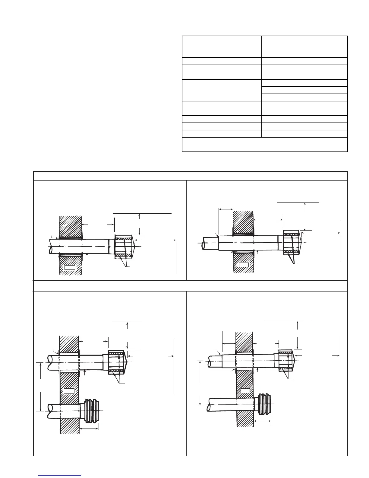
Horizontal Vent Terminal Clearances (See Figure 19)
Wall
Pitch flue pipe
down toward outlet
1/4 per foot for
condensate drainage.
Note position of
vent cap openings.
18
(457mm)
minimum
6 ft (1829mm)
minimum
3 ft (914mm)
minimum
Roof or building overhang
Parapet or adjoining building
Clearance to be
as specified on
Type B (double
wall) vent pipe
Follow the
instructions
on page 14
to join double
wall and single
wall pipe and
to attach a vent
cap to double
wall pipe.
6 (152mm)
minimum
Wall
Approved
clearance
thimble is
required
when flue
pipe extends
through
combustible
material.
18
(457mm)
minimum
Pitch flue pipe
down toward outlet
1/4 per foot for
condensate drainage.
Note position of
vent cap openings.
6 ft (1829mm)
minimum
Parapet or adjoining building
Roof or building overhang
3 ft (914mm)
minimum
Wall
18 (457mm)
minimum
18
(457mm)
minimum
Fresh air intake cap
9
229mm
maximum
Pitch flue pipe
down toward outlet
1/4 per foot for
condensate drainage.
Note position of
vent cap openings.
Roof or building overhang
3 ft (914mm)
minimum
6 ft (1829mm)
minimum
Parapet or adjoining building
Approved
clearance
thimble is
required
when flue
pipe extends
through
combustible
material.
Note position of
vent cap openings.
6 ft (1829mm)
minimum
3 ft (914mm)
minimum
18
(457mm)
minimum
Clearance to be
as specified on
Type B (double
wall) vent pipe
Fresh air intake cap
9 (229mm)
maximum
6 (152mm)
minimum
Pitch flue pipe
down toward outlet
1/4 per foot for
condensate drainage.
Roof or building overhang
Parapet or adjoining building
Follow the
instructions
on page 14
to join double
wall and single
wall pipe and
to attach a vent
cap to double
wall pipe.
18 (457mm)
minimum
Wall
Figure 19A - Horizontal Vent Terminal Arrangements (drawings are not proportional; read all information)
Figure 19B - Horizontal Vent Terminal/Air Intake Arrangements (drawings are not proportional; read all information)
Structure
Minimum Clearances for Vent
Termination Location (all
directions unless specified)
Forced air inlet within 10 ft (3.1m) 3 ft (0.9m) above*
Combustion air inlet of another
appliance
6 ft (1.8m)
Door, window or gravity air inlet 4 ft (1.2m) horizontally
(any building opening) 4 ft (1.2m) below
3 ft (0.9m) above
Electric meter, gas meter ** and
relief equipment
4 ft (1.2m) horizontally
Gas regulator ** 3 ft (0.9m)
Adjoining building or parapet 6 ft (1.8m)
Grade (ground level) 7 ft (2.1m) above
*This heater is approved for installation as illustrated in Figure 19B.
**Do not terminate the vent directly above a gas meter or service regulator.
SINGLE WALL - Single wall vent run and single wall
terminal end
DOUBLE WALL - Single wall vent run and double
wall terminal end
SINGLE WALL - Single wall vent run; single wall
terminal end; and single wall fresh air intake
DOUBLE WALL - Single wall vent run; double wall
terminal end; and single wall fresh air intake
 Loading...