Form RZ-NA-I-TR, Page 14
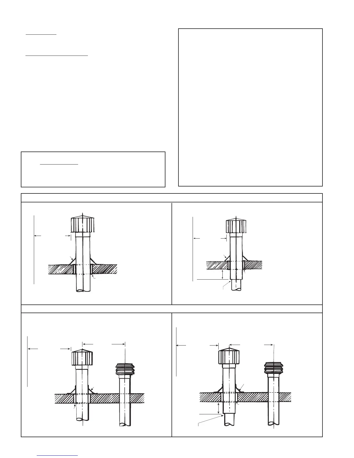
6 ft
(1829mm)
minimum
Roof Flashing
Roof pitched
from 0 to 45°
6 (152mm)
minimum
Clearance to be
as specified on
Type B
(double wall)
vent pipe
Follow the instructions above to join double wall and single
wall pipe and to attach a vent cap to double wall pipe.
Vertical flue extension
to be 6 (152mm)
higher than anticipated
snow depth but no less
than 24 (610mm) above
the roof. Vertical pipe
extension must be
insulated.
Parapet or adjoining building
3 ft (914mm)
minimum
If the fresh air intake is
within 10 feet (3M) of the
flue extension, the flue
extension must be at least
12 (305mm) higher than
the fresh air intake.
Fresh air intake must
be 6 (152mm)
higher than antici-
pated snow depth.
6 ft
(1829mm)
minimum
Roof Flashing
Vertical flue extension must
be 6 (152mm) higher than
anticipated snow depth but no
less than 24 (610mm) above
the roof. Vertical pipe extension
must be insulated.
Parapet or adjoining building
Roof pitched
from 0 to 45°
An approved clearance
thimble for single-wall
vent pipe is required when
the flue piepe extends
throu
h combustible maerial.
Figure 18A - Vertical Vent Terminal Arrangements (drawings are not proportional; read all information)
6 ft
(1829mm)
minimum
Roof Flashing
Roof pitched
from 0 to 45°
Vertical flue extension
to be 6 (152mm) higher than
anticipated snow depth but no
less than 24 (610mm) above
the roof. Vertical pipe extension
must be insulated.
Parapet or adjoining building
Follow the instructions above to join double wall and
single wall pipe and to attach a vent cap to double wall pipe.
Clearance to be as specified on
Type B (double wall) vent pipe
6 (152mm)
minimum
Figure 18B - Vertical Vent Terminal/Air Intake Arrangements (drawings are not proportional; read all information)
6 ft
(1829mm)
minimum
Roof Flashing
Roof pitched
from 0 to 45°
An approved clearance
thimble for single wall
vent pipe is required
when the flue pipe extends
through combustible
mat
rial
Vertical flue extension
to be 6 (152mm)
higher than antici-
pated snow depth
but no less than 24
(610mm) above the roof.
Vertical pipe extension
must be insulated.
3 ft (914mm)
minimum
Fresh air intake must
be 6 (152mm)
higher than antici-
pated snow depth.
If the fresh air intake is
within 10 feet (3M) of the
flue extension, the flue
extension must be at least
12 (305mm) higher than
the fresh air intake.
Parapet or adjoining building
INSTRUCTIONS FOR DOUBLE WALL PIPE INSTALLA-
TION: Material Required: Double wall (Type B) Vent Pipe (Note:
Use only one piece of double wall vent pipe.); a thimble designed for
double wall pipe (if construction is combustible); six 3/4" long
sheetmetal screws; the vent cap; and a tube of silicone sealant.
11. Venting (cont'd)
6. Condensation - If single-wall vent pipe is exposed to cold air or run
through unheated areas, it must be insulated. Where extreme conditions
are anticipated, install a means of condensate disposal.
7.
Vent Terminal and Vent Cap - The vent system must be terminated
with the type of vent cap approved for use with this heater. The vent
terminal and vent cap must be the same diameter as the vent run. Use
either an optional (Option CC1) vent cap or equivalent such as a Type L
Breidert Air-x-hauster
®
. (Type L Air-x-hauster
®
is a trademark of The G.
C. Breidert Company.) A different style vent cap could cause nuisance
problems and/or unsafe conditions.
See the illustrations in Figures 18 and 19 for requirements of both verti-
cal and horizontal vent termination. Using either single or double wall
vent terminals is illustrated. Many local codes require the use of double-
wall (Type B) vent for the portion of vent pipe (terminal) on the outside
of the building.
If double-wall pipe is used in the vent terminal, follow the instructions
below to attach the vent cap and to connect the double-wall pipe to the
single-wall vent system.
Instructions to attach VENT CAP to DOUBLE WALL (Type B)
VENT TERMINAL
Look for the "flow" arrow on the vent pipe. Attach the vent cap to the
"exhaust" end of the double wall pipe.
1) Slide the vent cap inside the pipe.
2) Drill a hole through the pipe and the vent cap. (Hole should be
slightly smaller than the sheet metal screw being used.) Using a 3/4"
long sheet metal screw, attach the cap to the pipe.
3) Repeat Step 2) drilling and inserting two additional screws evenly
spaced (120° apart) around the pipe.
Instructions to connect the SINGLE WALL VENT system to a
DOUBLE WALL (Type B) VENT TERMINAL:
1) Slide the single wall pipe inside the inner wall of the double-wall
terminal pipe.
2) Drill a hole through both walls of the double wall pipe and the single
wall pipe. (Hole should be slightly smaller than the sheet metal screws
being used .) Using a 3/4" long sheet metal screw, attach the two pieces
of pipe. Do not overtighten.
3) Repeat Step 2) drilling and inserting two additional screws evenly
spaced (120° apart) around the pipe.
4) To seal the annular opening (the gap between the single and double
wall pipe), run a large bead of silicone sealant in the opening. The bead
of sealant must be large enough to seal the opening, but it is not
necessary to fill the full volume of the annular area.
SINGLE WALL - Single wall vent run and single wall
terminal end
DOUBLE WALL - Single wall vent run and double
wall terminal end
SINGLE WALL - Single wall vent run; single wall
terminal end; and single wall fresh air intake
DOUBLE WALL - Single wall vent run; double wall
terminal end; and single wall fresh air intake
 Loading...