Form RZ-NA-I-TR, Mfg No. 121027 Rev 5,
Page 13
Specific Vent Requirements
1. Vent Pipe Length - The vent lengths shown in the Vent Table are based on
(1) the maximum permissible resistance to flow at which each model size will
operate and (2) the potential for continuous condensing. Condensing in the
vent pipe should not occur after equilibrium has been reached when the sur-
rounding ambient temperature is 60°F unless otherwise noted (See Require-
ment No. 6, Condensation).
Do not exceed maximum vent length. Minimum vent length is 5 feet.
Use equivalents listed when calculating for elbows and optional dual vent
adapter (Option CC5).
12. Venting
Venting must be in accordance with the National Fuel Gas Code Z223.1 (NFPA
54) or CAN/CGA B149.1 and B149.2, Installation Code for Gas Burning
Appliances and Equipment, and all local codes.
ANSI standard applicable to this heater does not require venting categoriza-
tion; if such a requirement existed, this heater would be in Category III. (Cat-
egory III appliances have a positive-pressure vent requiring a gastight sealed
vent system.) These tubular infrared heaters have been designed to operate
safely and efficiently with vent pipe lengths shown in the Vent Length Table.
Vent systems may either be vertical or horizontal. The type of vent required
depends on the size of heater and the vent run configuration.
Type of Vent Required by Vent Category
Model Sizes 50-125 150-200
- with a Horizontal Vent Run Category III Category III
- with a Vent Run that is at least one-half Category I
vertical (using equivalent lengths from the or Category III
Vent Length Table below) Category III
- with a Dual Vent Adapter (Option CC5) Category III Category III
Vent terminal end may be either single-wall pipe or double-wall pipe. A vent
terminal cap is required. Install a vent cap supplied as Option CC1 or a fully-
comparable, field-supplied vent terminal cap such as a Type L Breidert Air-x-
hauster
®
. (Type L Air-x-hauster
®
is a trademark of The G. C. Breidert Com-
pany.) Dual venting of two units is permissible when using an Optional Dual
Vent Kit (Option CC5).
Comply with the specific requirements and instructions in the following para-
graphs.
2. Vent Pipe Type - Use only 4-inch diameter vent pipe.
If the type of vent required is Category III (refer to table
above), use either a vent pipe approved for a Category III heater or
appropriately sealed 26-gauge galvanized steel or equivalent single-
wall pipe.
If the type of vent required is Category I (refer to table above),
unsealed 26-gauge galvanized steel or equivalent single-wall pipe
or double-wall (Type B) vent pipe may be used.
3. Vent Pipe Joints - Vent system joints depend on the vent cat-
egory and the type of pipe being used.
If installed as a Category III appliance and using single-wall
vent pipe, join pipes with at least two non-corrosive screws per
vent pipe joint and seal all joints to prevent leakage of flue gases
into the building. For sealing joints, the use of Aluminum or
TEFLON
®
(trademark of DuPont Corporation) tape suitable for
550°F is recommended (required in California). Vent tape of this
type is available from the heater manufacturer as P/N 98266.
If installed as a Category III appliance and using vent pipe
specifically approved for Category III vent systems, follow
the pipe manufacturer's instructions for proper sealing.
If installed as a Category I appliance (allowed only for Sizes
50-125 when at least half of the total equivalent length of the
vent system is vertical), use at least two non-corrosive screws per
vent pipe joint on single-wall pipe or follow the pipe manufacturer's
instructions for joining double-wall pipe.
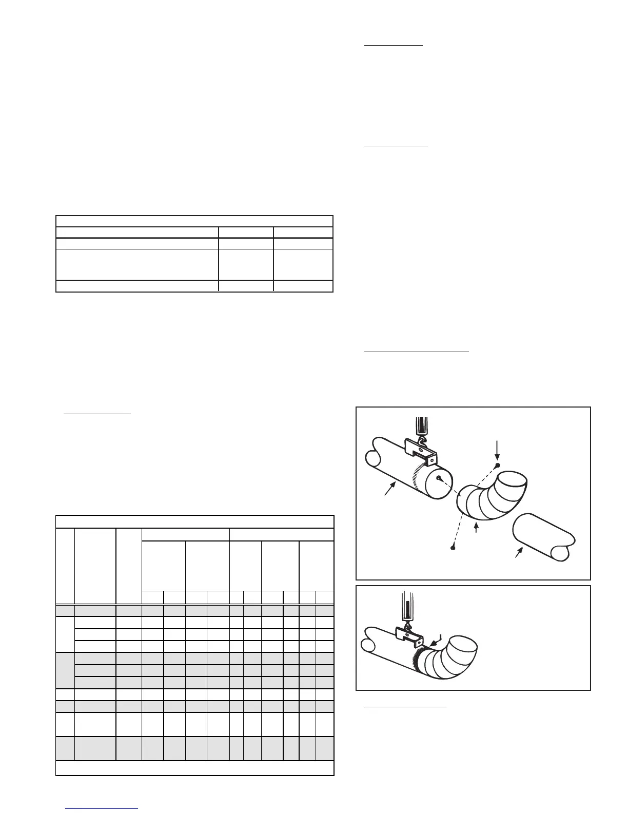
4.
Attach Vent Pipe to Heater - The last heat exchanger section
(tail pipe) is designed to permit direct attachment of a vent pipe,
either straight or elbow.
Attach metal vent pipe using three non-corrosive screws spaced
equal distance apart. See Figures 17A and 17B.
Suspended
Tail Pipe
Non-corrosive sheetmetal
screws spaced approximately
120° apart
Single wall straight pipe section
Single wall
elbow or
Figure 17A -
Attach Metal
Vent Pipe to
Tail Pipe
If the system includes a "U" or "L" heat exchanger tube, the reflectors on
either adjacent side of the "U" or "L" reflector cannot be rotated and must
remain horizontal. All reflectors in a section or leg of the tubular system
should be at the same angle.
Tape joint with high temperature
aluminum tape or seal with high
temperature silicone rubber sealant.
Figure 17B - Seal
Tail Pipe and Vent
Pipe Joint
5. Vent System Support - Vent pipe support is especially impor-
tant with the tubular infrared system because of the added stress
which may be caused by expansion and contraction of the overall
system. Support lateral runs a minimum of every six feet using
non-combustible material, such as steel strap or chain. Do not rely
on the heater for support of either horizontal or vertical vent pipe.
Vent Length Equivalent Length for
Max Min Max Min ft M ft M ft M
50 20, 25, 30 4 20 5 6.1 1.5 3 0.9 1-1/2 0.5 3 0.9
20, 25 4 45 5 13.7 1.5 6 1.8 3 0.9 6 1.8
75 30, 35 4 35 5 10.7 1.5 5 1.5 2-1/2 0.8 5 1.5
40 4 20 5 6.1 1.5 3 0.9 1-1/2 0.5 3 0.9
30, 35 4 45 5 13.7 1.5 6 1.8 3 0.9 6 1.8
100 40, 45 4 35 5 10.7 1.5 5 1.5 2-1/2 0.8 5 1.5
50 4 20 5 6.1 1.5 3 0.9 1-1/2 0.5 3 0.9
125 40, 45, 50 4 60 5 18.3 1.5 12 3.7 6 1.8 12 3.7
150 50, 55, 60 4 60 5 18.3 1.5 12 3.7 6 1.8 12 3.7
175
50, 55, 60,
65, 70
4 60 5 18.3 1.5 12 3.7 6 1.8 12 3.7
200
50, 55, 60,
65, 70
4 60 5 18.3 1.5 12 3.7 6 1.8 12 3.7
*
Must be deducted from the total vent length of
each
heater.
Vent Length Table for Tubular Infrared Heaters
feet M
90°
El bow
45°
El bow
Dual
Vent
Adapter
Box
*
Input Size (000)
Straight
Tube
Le ngth
(ft)
Vent Diameter
(inches)