Do you have a question about the THOMSON DPL 800VD and is the answer not in the manual?
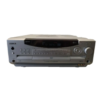
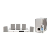
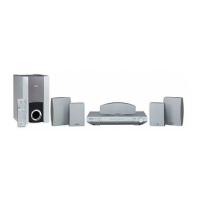
Specifies the main type of audio/video apparatus.
Details the required AC input voltage and frequency.
Defines the audio frequency range for front and rear amplifiers.
Measures the audio signal distortion levels.
Specifies the range between the loudest and quietest signals.
Details input signal levels and test patterns for receiver testing.
Lists pin functions for various audio and video connectors.
Warns about invisible laser radiation and direct exposure.
Instructions to prevent damage from electrostatic discharge.
Highlights critical safety components and replacement requirements.
Illustrates the radio frequency and intermediate frequency circuitry.
Details the digital signal processing circuitry and modules.
Steps for safely servicing the optical pickup unit.
Instructions for removing and reinstalling the disc tray.
Illustrates the wiring connections between various circuit boards.
Overview of major functional blocks and signal flow.
Diagram of the unit's power supply and distribution circuit.
Details digital signal connections and interfaces.
Illustrates the SCART connector pin assignments and signal routing.
Component placement diagram for the power supply/speaker board.
Component placement diagram for the digital input board.
Shows component placement and identification on the MCU board.
Component layout for the front panel controls and display.
Layouts for ON/OFF, Standby, and other switch PCBs.
Diagram showing connections to the main microcontroller.
Schematics for the Front Board and Key Data Board.
Component layout for the DPL800VD Front Board.
Layouts for various front panel control and switch PCBs.
Schematic diagram for the CD motor control circuitry.
Lists part numbers and identifiers for various modules.
Lists part numbers for connectors and miscellaneous components.
Part numbers for chassis, presentation elements, and controls.
Lists part numbers for various CD mechanism components.
Visual representation of the CD mechanism assembly.
Exploded view showing chassis and presentation part locations.
Analysis of 'Disc Error' messages and potential causes.
Instructions for installing a modified frame hinge and plastic arm kit.
Explanation of the IRIS code for warranty claims and fault reporting.
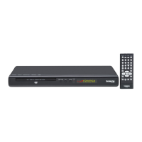
| Type | DVD player |
|---|---|
| Playable Media | DVD, CD, MP3, JPEG |
| Video Output | SCART |
| Connectivity | SCART |
| Power Supply | AC 230V, 50Hz |