Rev E June 2023
Appendix A Rear Panel Connector Pinout Details
Page 48
Appendix A Rear Panel Connector Pinout Details
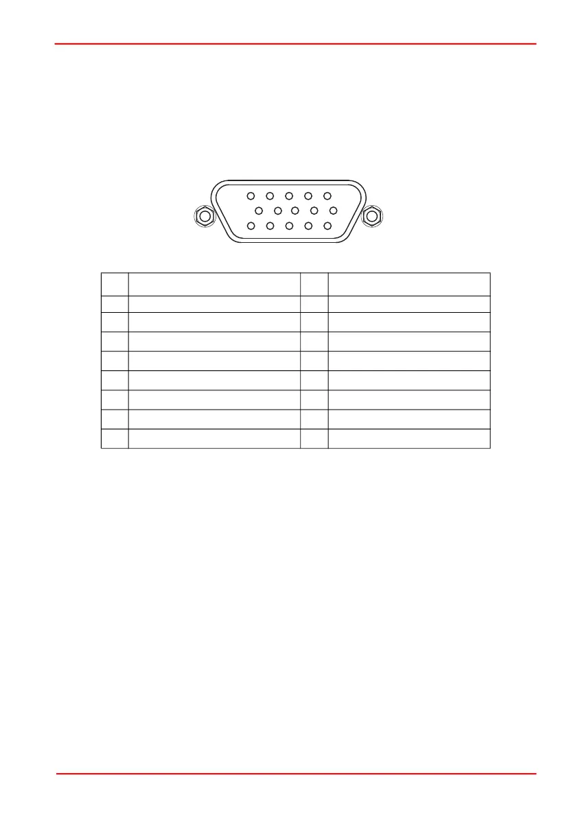
A.1 Rear Panel USER IO Connector
The ‘USER IO’ connector is for future use and no functionality is implemented at this
time.
Notes.
a
The OW-A/B/C/D pins are for future use with one wire interface to actuators and are
not implemented at this time.
b
LS_ENC pins are active in association with selected drive output channels.
For example, if Ch1 and/or Ch2 selected then LS1A/LS1B and LS2A/LS2B are the
active limit switch inputs. If Ch3 and/or Ch4 selected then LS3A/LS3B and LS4/LS4B
are the active limit switch inputs.
Fig. A.1 USER I/O Connector Pin Identification
Pin Description Pin Description
1 0 V 9 0 V
2
OW-A
a
10 +5 V
3
OW-B
a
11
Limit Switch 3A/Encoder 3A
b
4
Limit Switch 1A/Encoder 1A
b
12
Limit Switch 3B/Encoder 3B
b
5
Limit Switch 1B/Encoder 1B
b
13
Limit Switch 4A/Encoder 4A
b
6
Limit Switch 2A/Encoder 2A
b
14
Limit Switch 4B/Encoder 4B
b
7
Limit Switch 2B/Encoder 2B
b
15
OW-D
a
8
OW-C
a