Page 6 MTN023788_D02
PM103x Optical Power Meter Interfaces Chapter 2 General Information
Chapter 3 Getting Started
Please inspect the shipping container for damage. Please do not cut through the cardboard. You might
need the box for storage or for returns.
If the shipping container seems to be damaged, inspect the contents for completeness and test the
PM103x mechanically and electrically. Keep the container for storage or in order to return the product
in case of future problems.
Verify that you have received the following items within the package:
3.1 Parts List
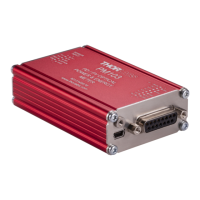
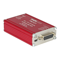
1. PM103x Optical Power and Energy Meter Interface
2. PM103 /A /U: USB Cable, Type A to Mini B, with Locking Screw, 1.5 m
3. PM103: DA-15 Connector and Connector Housing
4. PM103E: RJ45 Patch Cable 1.5 m, Phoenix DMC connector DFMC 0,5/7-ST-2,54 with 2x7
pins
5. Quick Reference
6. Certificate of Calibration
Chapter 4 Operating Instructions
4.1 How To
This chapter describes how to install the PM103x for standard measurements.
4.1.1 PM103x Setup
· Download and install the Optical Power Monitor software on the device that will be used to
control the power meter interface (PC, laptop or tablet).
Note
Install the software prior to connecting the power meter interface to the PC (see Software ).
· Connect the PM103x to a PC (Status LED turns yellow) or other power source (status LED power
supply turns green) via the USB port or with power over ethernet in case of the PM103E.
o The PM103 accepts external power supplies with 5 V to 36 V via the DA-15 interface (see Pin
Output Connector DA-15 ). When connecting the USB port while using an external power
supply via the DA-15 port, connecting the USB port will automatically switch to the 5 V power
supply via USB.
o The PM103E accepts external power supplies with 5V to 36 V via the phoenix DMC connector
(see Phoenix Output Connector DMC 0,5/7 ).
o The status LED for the power supply is green when connected to an external power supply via
the DA-15 connector or in case of the PM103E, the phoenix DMC connector.
· Connect the PM103x to a readout instrument (PC) using the USB cable or a matching cable for the
respective output port (SMA or DA-15). For PM103A and PM103, please provide cables.
· Connect a suitable sensor to the PM103x.
The sensor status LED indicates, when a sensor has been detected (green) or when no sensor or
no recognizable sensor is connected (red).
The Power Meter is now ready for operation and is recognized by the OPM software.
27
35
35
7