Page 34 MTN023788_D02
PM103x Optical Power Meter Interfaces Chapter 5 Specifications
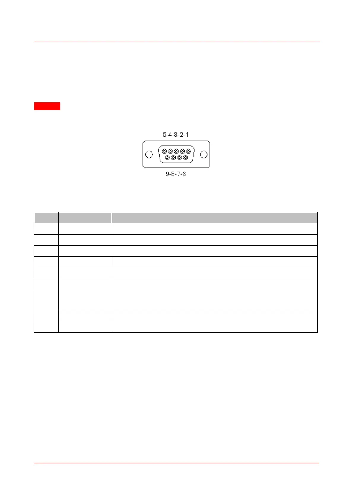
5.3 Pin Sensor Connector
The sensor connector allows the access of all Thorlabs “C-type" photodiode and pyroelectric sensors.
The power meter interface uses the sensor calibration data, stored in the sensor connector, to calculate
the corresponding actual power levels.
Additionally, the PM103x is capable to support custom made detectors. Please read the following
instruction prior to connecting a self made sensor.
Warning
Pin 2 is uniquely used for the EEPROM Digital I/O (memory in Thorlabs sensor heads) and MUST NOT be
used. Connecting this Pin may cause malfunction of the PM103x.
Pin-out of the DE-9
female connector
(female)
+5 V; Max Current 50 mA from this Pin
Sensor Memory for the Calibration Data
Analog Ground for Photodiode, Pyroelectric Sensor, NTC
Pyroelectric Sensor Input
Digital Ground for EEPROM and 5 V Output
Sensor Recognition, NTC Input. For Custom Sensors: Connect via a 1 kW –
10 kW Resistor to Pin 3 (AGND) to Enable a Custom Sensor