Page 14 MTN023788_D02
PM103x Optical Power Meter Interfaces Chapter 4 Operating Instructions
4.2.2.11 Analog Output
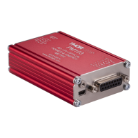
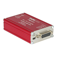
PM103
The PM103 has two analog outputs, AO1 and AO2 (please see Pin assignment ).
The Analog Output ports provide the amplified photo-diode current or the pyroelectic sensor voltage,
depending on the sensor. The signal from the analog output AO1 is not wavelength- or zero- corrected.
The signal is measurement range dependent and can be calculated to:
AO1: The AO1 (DA-15 Pin 4) delivers the amplified direct real analog signal without a Digital-Analog-
Converter (DAC). Therefore, the AO1 delivers a proportional output voltage for each measurement
range. This analog output voltage can range from -0.25 V to +2.5 V. The real analog signal is not
wavelength- or zero- corrected and offers the full bandwidth (up to 1 MHz) without quantization error.
Note
The bandwidth is in accordance with the settings of the sensor and power meter.
AO2: The AO2 (DA-15 Pin 5) delivers a range independent voltage which is DAC controlled. The output
voltage is proportional to a configured value in V/W or V/J. This constant can be adjusted via the OPM
software or, for custom made software, using the SCPI/driver commands in the WYOA for PM103x. The
constant can be set in the Thorlabs software OPM under the Settings tab: AO2 Responsivity. The signal
of the AO2 is generated with a 16-bit DAC with an update rate of 1 kHz. The analog output voltage can
range from -0 V to +2.5 V.
The analog signal following the DAC is of advantage when large signal dynamics are expected because
the DAC range changes and the output signal stays largely the same. Additionally, the output signal is
wavelength corrected and corrected regarding the sensor calibration data.
PM103A
The PM103A has two analog output ports with a SMA output connectors. The functions match the
function of AO1 and AO2 of the PM103 respectively.
4.2.2.12 Autonomous Operation to Analog Output
Power meters PM103 and PM103A can be run autonomously by simply connecting a power supply and
using one of the analog output ports . In that case, no control device is required.
4.2.2.13 NTC Input
To monitor the temperature in a test environment, the PM103 has an NTC Input (DA-15, Pin 14) which
allows connection of an NTC thermistor. To connect the ground of the TSP-TH, please use one of the
GND connectors DA-15 Pin 10 through Pin13. The measurement range is 0.1 – 100 kW. The set range R0
and the bandwidth B for the NTC thermistor can be adjusted in the OPM software or through SCPI
commands. The default settings are 10 kW and 3988 K to directly access the TSP-TH temperature probe.
The measurement range with the PM103 is then -10 °C to 80 °C with the TSP-TH.
35
14