Ø1/4" Shutters and Controller Chapter 4: Setup and Operation
Page 6 TTN042240-D02
Chapter 4 Setup and Operation
4.1. Connection Guide
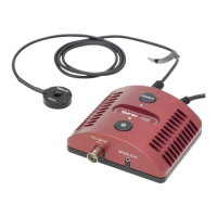
1. Remove components from the case.
2. Secure the SHB025(T) shutter head to your setup using the two mounting
holes or a mounting adapter (sold separately).
3. Connect the AC power to the power supply and then connect to the AC
power outlet. The SHB025(T) are each supplied with an external AC-DC
switching power supply rated at 100 – 240 VAC, 47 – 63 Hz, and 5 VDC
@ 2.4 A maximum output.
4. Place the controller on a flat surface. Connect the mini-DIN connector from
the shutter head, with the arrow on the connector pointing up, into the
controller.
5. Turn the unit on by pressing the power button.
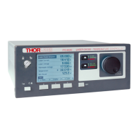
4.2. Manual Shutter Operation
There are two LEDs on top of the unit. The LED next to the power button is green
when the power is on or off when the power is off. The LED next to the enable
button indicates the status of the controller as shown in the table below.
Note that when the shutter is closed and in unprotected mode, the LED will be off.
Additionally, unplugging the shutter from the wall outlet will not change its mode,
so if it is in Unprotected Mode and unplugged, it will still be in Unprotected Mode
when plugged back in again. See Section 4.3.2 for more information on
Unprotected Mode.
WARNING
The SHB025(T) shutters can exceed temperatures of 70 degrees Celsius when
operated, which can burn the skin. For safety, allow approximately 5 minutes of
cool down after operation before handling.
The shutter generally defaults to the closed position. The following table outlines
the various conditions that will change the shutter's state. For more information on
the meaning of the LED colors and modes, please see the Section 4.6.2.