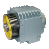
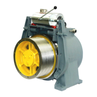
OPERATING MANUAL 4. MOUNTING OF MACHINE
ThyssenKrupp Aufzugswerke GmbH 34 Issue 06.2004
Connection of brake:
Voltage supply of release coils and control switches
The brake release coils are located in the connection box (fig. 10 pos. 5) at
the front brake side.
Connect four-conductor cable - cores 1; 2 (terminals 1; 2) = brake coil D and
cores 3;4 (terminals 3; 4) = brake coil C - and brake circuit.
Connection of screened six-core cable from connection box (cores 1;2
(terminal 6; 7) = temperature monitoring brake) and motor temperature
monitoring with evaluator to be made by the customer. The voltage applied
shall not exceed 2.5 V.
Cores 3; 4 (terminals 8; 9) = brake monitoring D;
and 5; 6 (terminals 10; 11) = brake monitoring C,
must be connected to the brake monitoring.
Note: it is recommended to adhere to the instructions and recommendations
of the brake manufacturer as the performance of the brake in service mainly
depends on the circuit selected. See chapter 8.3.
Terminal
Connection
11
10
Brake monitoring D
9
8
Brake monitoring C
7
6
Thermal monitoring
brake
5
Series connection Th
4
3
Brake connection
brake D
2
1
Brake connection
brake C
Fig. 11