OPERATING MANUAL 7. MAINTENANCE
ThyssenKrupp Aufzugswerke GmbH 50 Issue 06.2004
Assembly:
• Clean but do not grease shaft end before you start mounting the
encoder.
The shaft end must be clean and free of grease
• Carefully turn and push fixing strap and female encoder component onto
shaft end in direction of arrow until the fixing strap is close to the brake
• Carefully tighten clamping bolt (pos.3) in the female component without
distorting the encoder.
The encoder housing must be easy to move on the shaft
• Turn encoder housing until the connecting cable is positioned properly.
• Align strap holes towards threaded holes of brake; screw-connect fixing
strap at brake
• Connect encoder connection to control
• Adjust encoder
Attention: when performing test and inspection works never switch the drive
on with the encoder unconnected; this can cause damage of electronic
components in the encoder.
Note: re-adjust the encoder with the pulse encoder being replaced or the
rotor position changed. Proceeding see operating manual of frequency
inverter.
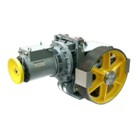
Fig. 18
1 Hexagon socket screw
2 Fixing strap
3 Brake housing
4 Encoder
5 Shaft end
6 Connecting line
7 Clamping bolt
1
5
1
4
3
2
6
7