PK-232 MBX – OPERATING MANUAL RADIO INSTALLATION
4/91 3-3 27
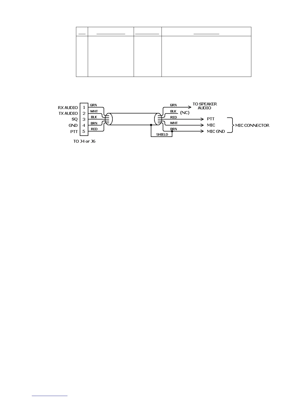
Pin Signal Name Wire Color Description
1
2
3
4
5
Receive audio
Microphone audio
Squelch input
Ground
Push-To-Talk
Shield/Drain Wire
Green
White
Black
Brown
Red
Silver
Audio from receiver to PK-232
AFSK from PK-232 to transmitter
Optional squelch input from radio
Audio and PTT common return
PK-232 keys transmitter
Shield of cable / Microphone Ground
Table 3-1 J4 and J6 Radio Port and Cable Connections
Figure 3-2 PK-232 to Radio Cable Connections
3.3.5 Begin Assembling your Radio Cable
Assemble all the tools, PK-232 Radio cable and connectors you will need for each radio
you wish to connect. You will probably also need a small soldering iron (20 – 40 watts)
and solder at your work area.
3.3.5.1 Prepare the Radio Cable
1. Locate one of the 5 ft. PK-232 radio cables included with your PK-232. Note that the
Radio cables may have been shipped as a single 10 ft. cable which should be cut in
half before use.
2. Prepare the bare end of one of the radio cables by removing an appropriate amount
of the jacket for the connector you will be attaching. Usually this is 1/2 to 3/4 inch.
3. Carefully remove the foil shield exposing the colored wires underneath. Be careful
not to nick or cut the shield wire.
4. Strip back 1/8 inch of colored insulation from the GREEN, RED, WHITE and BROWN
wires.
NOTE: The BLACK wire is the squelch input and normally not used. The black wire is
only needed for Packet operation if the channel you plan to operate on is
used for both voice and data. If you need this connection, strip away 1/8
inch of BLACK insulation as done with the other four wires. If this wire is not
needed, then leave the insulation intact.
3.3.5.2 Verify the Connection Points with Your Manual
Look at the connector closely (with a magnifying glass if necessary) and locate pin 1.
Compare this to the location of pin 1 on the connector drawing in your transceiver's ma-
nual and also in APPENDIX E. This is important as some diagrams show the connector
from the inside of the transceiver, not the outside of the plug you are wiring. This will help
insure that the plug is not wired backwards.