EasyManua.ls Logo

Toa RM-1200 - 7 Connections; Notes on Connections; Connection of the RM-1200 to the Rack-Mounted Emergency PA System FS-971 Series

Toa RM-1200
20 pages
Print Icon
To Next Page IconTo Next Page
To Previous Page IconTo Previous Page
Loading...
11
7. CONNECTIONS
7.1. Notes on Connections
The maximum cable length between the main rack and the RM-1200 is 800 m.
Use cables with line resistance of less than 10.
Use twisted paired cable for bus lines.
Use twin shielded cables for signal lines.
Be sure to connect the RM-1200's bus line to BUS 1 terminal.
Be sure to match the polarity of bus lines.
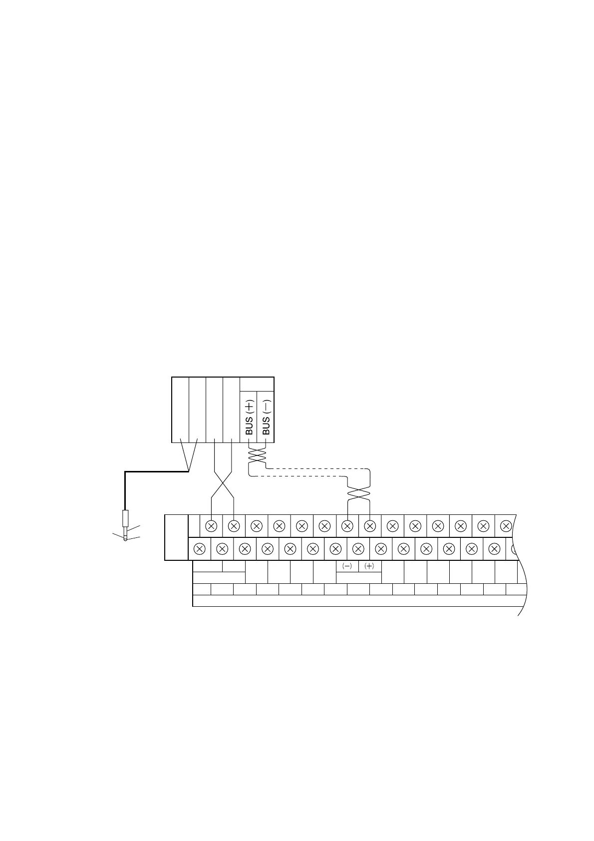
7.2. Connection of the RM-1200 to the Rack-Mounted Emergency PA System
FS-971 Series
Connect the remote control unit to the Junction
Panel JP-0410 in the main rack. Up to eight
remote control units can be connected per
junction panel.
H
C
24V
GND
1
E
H
C
JP-0410 front panel middle row terminal block
GND
GND
GND GND
GND
GND
24 V
CHIME
ACTI
GEM RM PWR
1
1
2
2
34 5 67 8
1
910
11 12
IN USE
REMOTE
REMOTE
TIMER
GEN RM BUS
PWR FAIL
CTRL
AUX CONTROL
To pre-amplifier
RM-1200 terminal block
Note
Do not connect E of the
phone plug to RM-1200.
Two-core shielded cable Twisted paired cable
Observe correct polarity
of bus lines.

Related product manuals