11
6. CONNECTING TO THE SX-2000 SYSTEM
Note
This function can be used only when all the versions of VM-3240VA/3360VA firmware, VM-3240E
/3360E firmware, and VM-3000 Setting Software are 2.00 or later and SX-2000 system ver. 3.00 or later.
6.1. General Description
Additionally connecting the VM-3240VAs/3360VAs to the SX-2000 system allows the SX-2000 system's
speaker line capacity to increase by 6 speaker lines per a single VM-3240VA/3360VA. In this case, the entire
system operates as shown below.
• The VM-3240VAs/3360VAs perform only 1-channel broadcasting (no standby amplifier).
• The SX-2000 checks for the VM-3240VA/3360VA amplifier failure, and the line failure between VM-
3240VA/3360VA amplifier and the SX-2000 amplifier.
• The VM-3240VA/3360VA checks for the speaker line failure.
Besides, adding the VP-2241 or VP-2421 amplifier to the SX-2000 system as a standby amplifier maintains
the general-purpose broadcast operation even if the VM-3240VA/3360VA fails.
Notes
• The VM-3240E/3360E cannot be used in this system.
• In the system where the VM-3240VA/3360VA and the SX-2000 system are combined, the VM-
3240VA/3360VA cannot be used as Emergency broadcast equipment.
• Never place the VM-3240VA/3360VA in emergency mode nor operate emergency EV, RM-300MF, and front
emergency microphone to prevent the entire system from malfunction.
• Audio Input 4 is reserved. (See the table of VM-3000 Settings.)
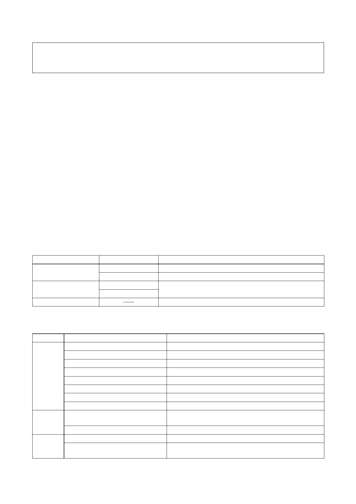
[Settings on the software when using the VM-3000 and SX-2000 in combination]
SX-2000 settings (Refer to the Setting Software manual attached to the SX-2000 unit.)
connected to VM-3240VA/3360VA.
RM-300MF should not be configured.
All outputs should be selected. (Default)