15
Step 4. Perform broadcasts from the SX-2000 system.
Audio signals input to the SX-2000 system enter the VM-3240VA/3360VA, return to the SX-2100AO,
and enter the VM-3240VA/3360VA again, and are finally output from the VM-3240VA's/3360VA's SP
OUT terminal. (Refer to the diagram below.)
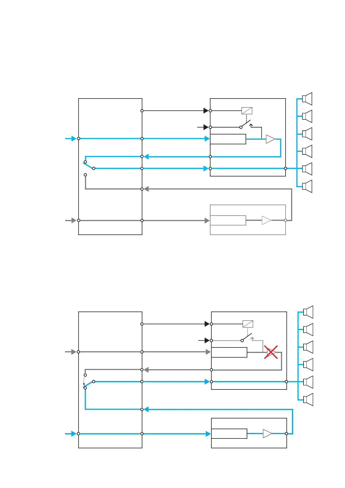
[Audio signal flow when the VM-3240VA/3360VA is connected to the SX-2000 system]
Audio sources being previously broadcast are shut off by a control signal from the SX-2100AO. Instead, audio
signals entering the VM-3240VA/3360VA from the SX-2100AO are broadcast.
6.5. Example When the VM-3240VA/3360VA Connected to the SX-2000 System Fails
If the VM-3240VA/3360VA fails, audio signals from the SX-2100AO being previously broadcast are shut off.
Instead, another audio signals from the SX-2100AO are broadcast by the standby amplifier.
Not broadcast because these audio signals are shut off when the control signal from the SX-2100AO is fed to the
VM-3240VA's/3360VA's CTR 8.