12
6.2. VP-200VX Installation in the VM-3240VA/3360VA
Step 1. Remove the screws securing the VM-3240VA's/3360VA's cover (3 pieces on each side, 2 on the top,
and 1 on the rear) to detach the cover. (Refer to p. 3.)
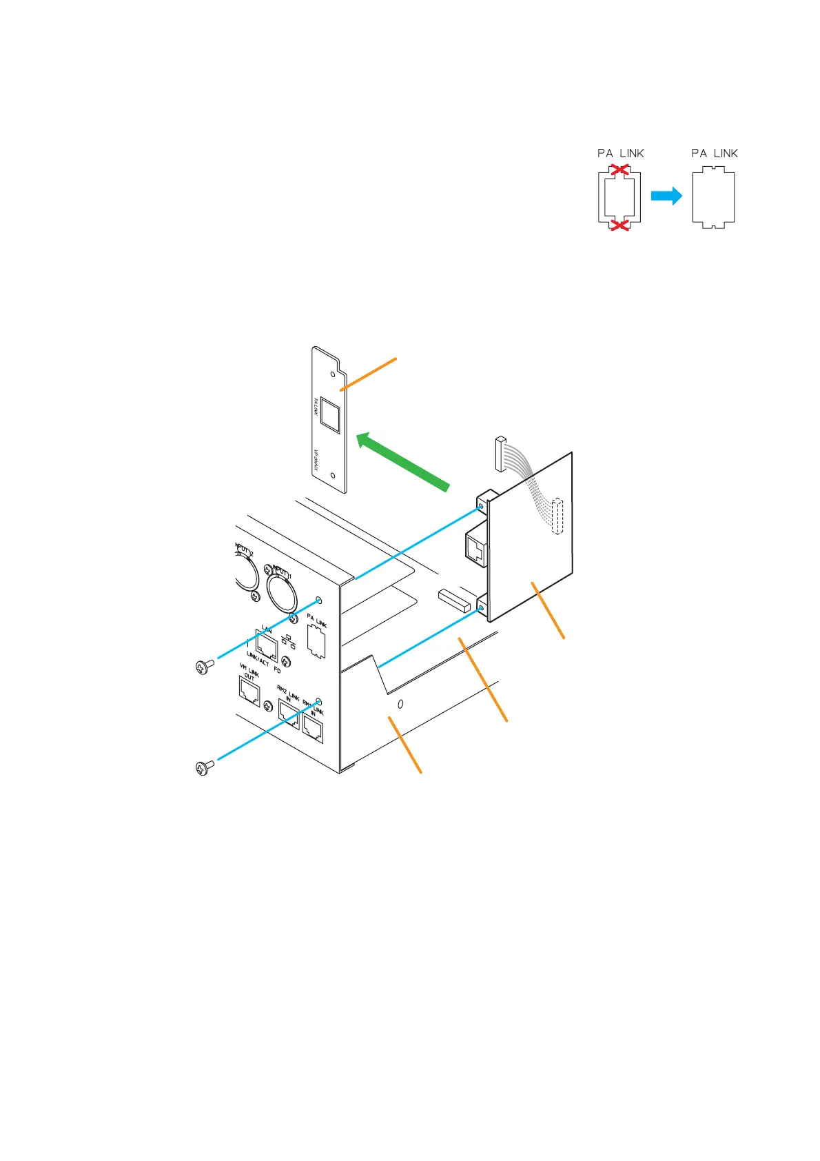
Step 2. Make an opening for mounting the PA LINK connector by removing the
knockout plate on the VM-3240VA's/3360VA's rear.
Step 3. Remove 2 screws on the VP-200VX's front panel to detach it. (This removed panel is not used.)
Install the VP-200VX (without the front panel) inside the VM-3240VA/3360VA, then secure it with the
removed screws.
Detach the front panel.
Step 4. Connect the VP-200VX's harness to the connector (CN1101) on the VM-3240VA's/3360VA's CPU
circuit board.
Step 5. Replace the VM-3240VA's/3360VA's cover by securing with the screws removed in step 1.