EasyManua.ls Logo

Toa VP-2000VX - Page 4

Toa VP-2000VX
16 pages
Print Icon
To Next Page IconTo Next Page
To Previous Page IconTo Previous Page
Loading...
4
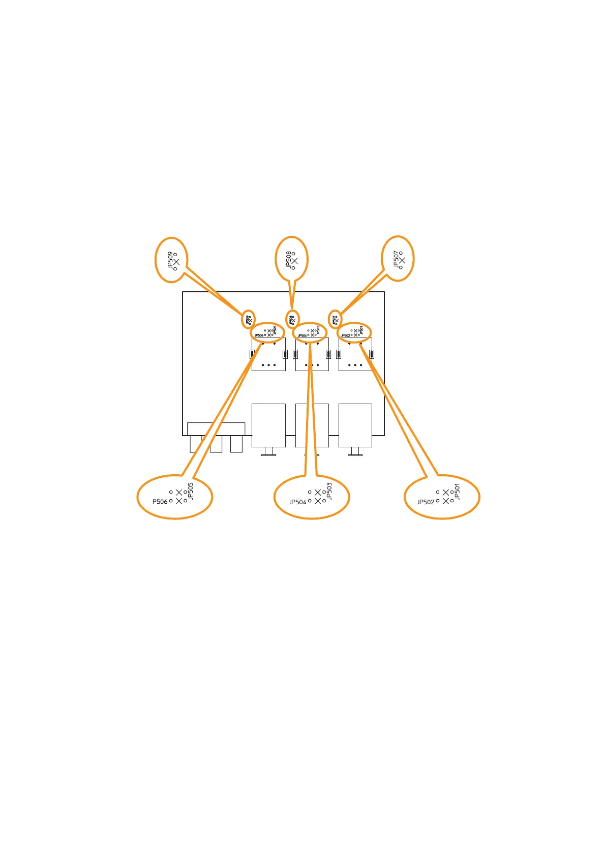
Step 4. Cut the jumper wires designated according to purposes referring to the PC board diagram showing
the jumper wire locations below.
4-1. To convert the electronically balanced input to a transformer-balanced one
Cut the jumpers (a), (b), or (c) corresponding to the transformer-installed input on the pc board.
4.2. To change the microphone input sensitivity
Cut the jumper (d), (e), or (f) corresponding to the desired MIC input on the pc board.
(a) JP501 and JP502:
Jumpers for input 1
balanced type conversion
(b) JP503 and JP504:
Jumpers for input 2
balanced type conversion
(c) JP505 and JP506:
Jumpers for input 3
balanced type conversion
(d) JP507:
Jumper for MIC input 1
sensitivity change
(e) JP508:
Jumper for MIC input 2
sensitivity change
(f) JP509:
Jumper for MIC input 3
sensitivity change
VM-3240VA/3360VA
(Front side)
4-2
4-1
Step 5. Replace the input PC board.
Step 6. Replace the cover.

Related product manuals