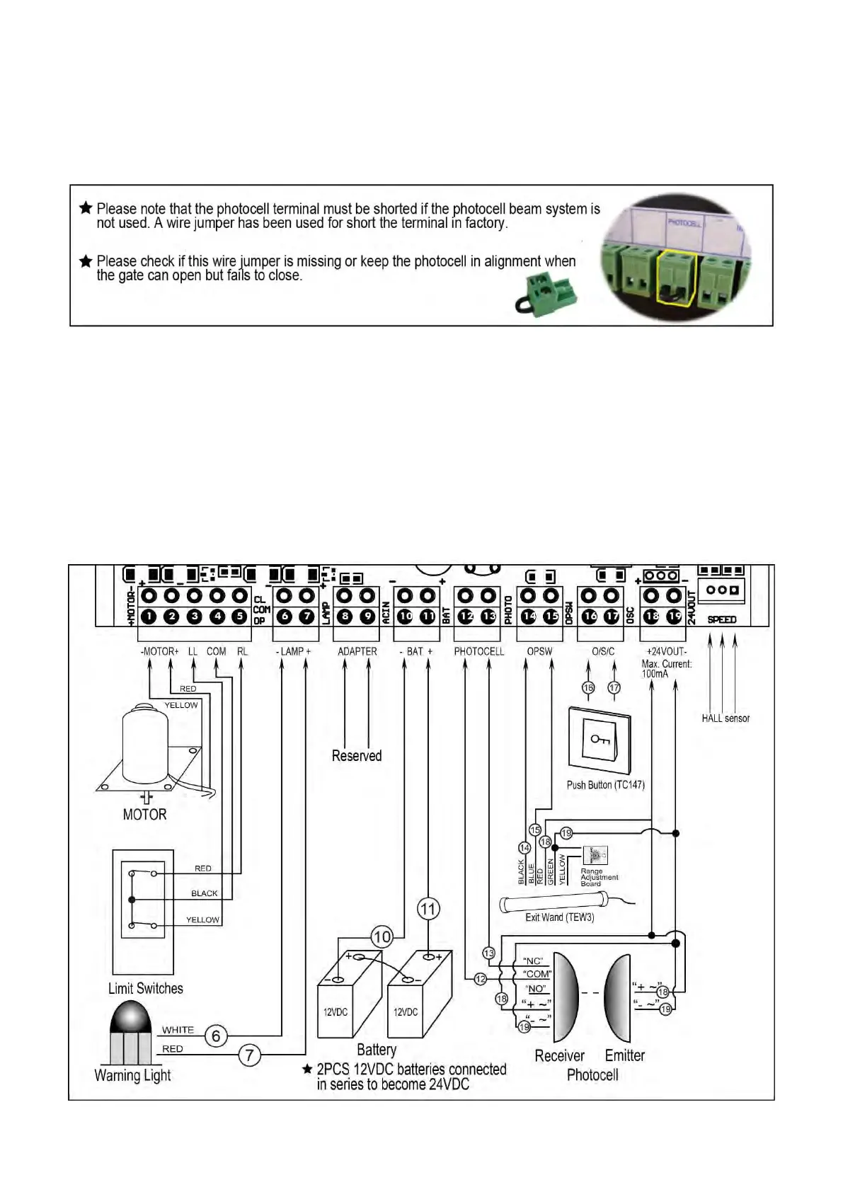
Use a 2-core cable to connect the “- ~” terminal of the photocell’s emitter to the “19” terminal, the “+ ~”
terminal to the “18” terminal. Also the “- ~” and “+ ~” terminals of the photocell’s receiver should be
connected to the “19” and “18” terminals in parallel.
Use another 2-core cable to connect the “NC” terminal of the receiver to the “13” terminal, the “COM”
terminal to the “12” terminal.
5. Push Button (optional)
The push button should be wired to the “16 and “17” terminals. No matter the polarity. The gate operator
works alternately by pressing the button (open-stop-close-stop-open).
6. Exit Wand (optional)
The BLACK wire of the exit wand should be connected into the “14” terminal.
The BLUE wire of the exit wand should be connected into the “15” terminal.
The RED wire of the exit wand should be connected into the “18” terminal.
The GREEN wire of the exit wand should be connected into the “19” terminal.
The sensitivity adjustment board should be wired to the GREEN wire and the YELLOW wire of the wand. No
matter the polarity.
 Loading...