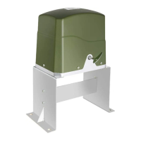
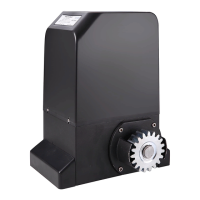
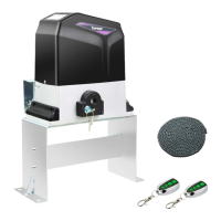
The TOPENS DKC2000(S/Y) is a sliding gate opener designed for automating the opening and closing of sliding gates. It is suitable for residential and light commercial applications, offering convenience and enhanced security. The opener is designed to be durable and reliable, providing smooth and consistent operation for various gate types.
Function Description:
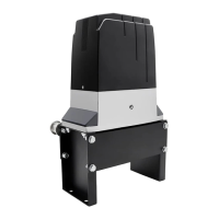
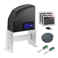
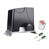
The primary function of the DKC2000(S/Y) is to motorize sliding gates, allowing them to be opened and closed automatically via remote control or other access devices. The system includes a motor unit, a control board, and various accessories for installation and operation. It is capable of handling gates up to a specified weight and length, ensuring broad applicability.
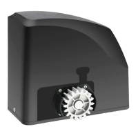
The opener operates by driving a chain that is attached to the gate, moving it along a track. It incorporates a limit switch system, utilizing magnets, to accurately determine the gate's open and closed positions, preventing overtravel and ensuring precise stopping. In the event of a power failure, the gate can be manually disengaged from the motor using a release key, allowing for manual operation.
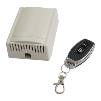
The control board is the central intelligence of the system, managing all operational aspects. It processes signals from remote controls, keypads, photocells, and other connected accessories to control the gate's movement. The control board supports various power modes, including AC electricity only, AC electricity with backup batteries, and battery power with solar panel charging, offering flexibility based on site requirements and power availability. For dual gate systems, one opener can be configured as a master to control a slave opener, enabling synchronized operation of two gates.
Usage Features:
The DKC2000(S/Y) offers a range of features designed to enhance user experience, safety, and operational flexibility:
- Optional Soft Start and Soft Stop: This feature allows the gate to begin and end its movement gradually, reducing wear and tear on the gate and opener components, and providing smoother, quieter operation.
- Midway Mode: This function enables the gate to open to a partial position, useful for pedestrian access without fully opening the gate. It can be activated via a remote control button.
- Quick Selection for Gate Open/Close Direction: The opener allows for easy configuration of the gate's opening and closing direction (left or right), accommodating different gate installations.
- Reliable Rolling Code Technology for Remote Control: The remote controls use rolling code technology, which changes the code each time the remote is used, enhancing security by preventing unauthorized access attempts through code copying.
- Emergency Release Key: In case of power failure or malfunction, a release key can be used to disengage the motor, allowing the gate to be operated manually.
- Obstruction Detection: The system includes safety features to detect obstructions during gate movement. During opening, the gate will stop if an obstruction is detected. During closing, it can be configured to either stop or reverse in case of obstruction, preventing damage or injury.
- Adjustable Auto-Close Function: Users can set a timer for the gate to automatically close after a specified period (1-250 seconds) once it has opened. This feature enhances security and convenience.
- Running Timeout Protection: The opener has a built-in running timeout protection (travel time + 45 seconds) to prevent the motor from continuously running if a limit switch fails or an obstruction prevents the gate from reaching its intended position.
- Reliable Electromagnetism Limit for Easy Adjustment: The magnetic limit switches provide precise and reliable positioning, and their adjustment is straightforward.
- Compatibility with a Wide Range of Accessories: The system is designed to integrate with various optional accessories, including warning lights, photocell beam systems, reflection photocell sensors, push buttons, exit wands, external receivers, and wired/wireless keypads. These accessories further enhance safety, convenience, and control options.
- Easy Installation: The manual emphasizes that the opener is designed for relatively easy installation, with minimum maintenance requirements. It provides detailed instructions for setting up the base plate, chain, magnets, and electrical connections.
- Master/Slave Configuration for Dual Gates: For properties with two sliding gates, the system supports a master/slave setup, where one opener controls the other, ensuring synchronized operation.
Maintenance Features:
Regular maintenance is crucial for ensuring the long-term safe and reliable operation of the DKC2000(S/Y) gate opener. The manual outlines several key maintenance checks to be performed every six months:
- Lubricate Shafts and Gears: Lubricating the moving mechanical parts helps reduce friction, prevent wear, and ensure smooth operation.
- Keep Opener Clean: Regularly cleaning the opener prevents dirt, dust, and debris from accumulating, which could interfere with its functionality.
- Check and Tighten Anchor Bolts: Ensuring that all anchor bolts are securely tightened prevents the opener from shifting or becoming unstable over time.
- Check for Loose or Corroded Wires: Inspecting electrical wiring for looseness or corrosion helps prevent electrical malfunctions and ensures consistent power supply and signal transmission.
- Ensure Opener is Correctly Terminated: Verifying that all electrical connections are properly terminated is essential for safe and reliable operation.
- Check Obstruction Function: It is critical to regularly test the gate's stop/reverse in case of obstruction function. If this safety feature is not working correctly, the opener should be taken out of service immediately until the cause of the malfunction is identified and corrected by qualified personnel. This ensures the safety of users, animals, and property.
The manual also advises users to save the manual for future reference and to contact TOPENS support via email or phone for any assistance or questions regarding installation, operation, or troubleshooting. This emphasizes the importance of proper installation and ongoing care to maximize the lifespan and performance of the gate opener.