CAL Optional Design
- 15-
Note 1: For order of additional spare parts, designate the type of the mechanical seal as a set, in
order to ensure preferable seal effect.
Note 2: Quantity of flushing liquid and pressure of it are different depending on use conditions,
refer to pump-datasheet.
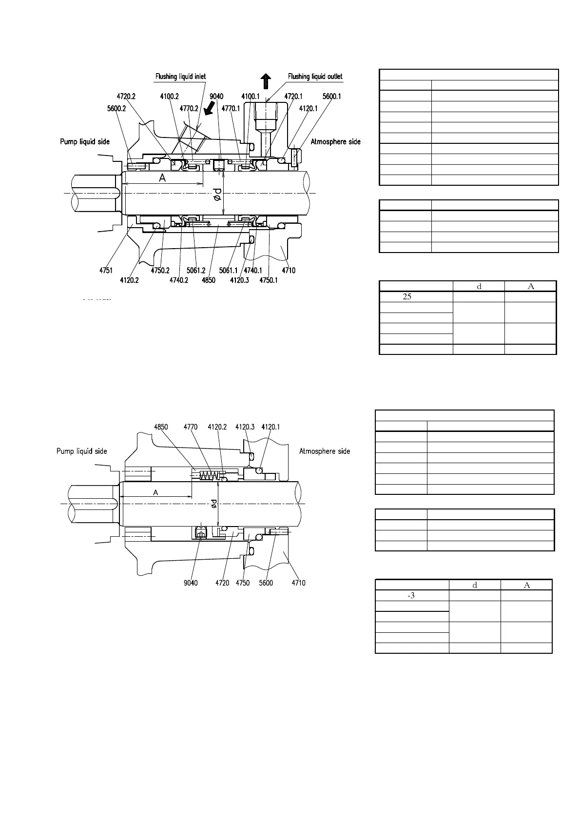
Parts table of a mechanical seal set
Parts No. Parts Name
4100.1,2 Packing
4120.1,2 O-ring
4720.1,2 Sealing washer
4740.1,2 Follower ring
4750.1,2 Seat
4770,1.2 Spring
4850 Stopper
5061.1,2 Spline ring
9040 Set screw
Mechanical seal type: LTW φd F/E
Parts table of a pump
Parts No. Parts Name
5600.1,2 Pin
4120 O-ring
4710 Seal cover
4751 Seat holder
Unit: mm
Shaft size
d A
25-360 24 44.5
35-470
45-470
45-470A
55-530
65-530 55 52.5
32
45
53
49.5
Fig 5.2-3 Construction of mechanical seal “LTW”
Conforming to DIN 24960 standard (Except for mechanical seal overall length)
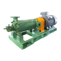
Note: For order of additional spare parts, designate the type of the mechanical seal as a set, in
order to ensure preferable seal effect.
Parts table of a mechanical seal set
Parts No. Parts Name
4120.1,2 O-ring
4720 Sealing washer
4750 Seat
4770 Spring
4850 Stopper
9040 Set screw
Mechanical seal typ: LA200-RF/RE/RK φd
Parts table of a pump
Parts No. Parts Name
5600 Pin
4120.3 O-ring
4710 Seal cover
Unit: mm
Shaft size
d A
25-360 24 39
35-470
45-470
45-470A
55-530
65-530 55 41.5
32
45
41
43
Fig 5.2-4 Construction of mechanical seal “LA200” (SiC × carbon)
4120.2