18-EN T75 DES
5. Mains connection
The control is wired in a ready-to-connect fashion using a
16A CEE plug and a cable with an approximate length of 1m in
compliance with Fig.
. Connect the control via an all-pole line
disconnecter ≥ 10 A complying with the specifications of
EN12453 to the house wiring system. In doing this, ensure that
the line disconnecter is easily accessible after the installation.
NOTICE
Checking the mains connection
• Ensure that on-site fusing of 10 A is avail-
able.
• Check whether the mains connection on
site complies with the pre-wired mains con-
nection of the control.
• If the mains connection shows any devi-
ations, the control must be rewired.
6. Motor connection line
Fig.
The motor connection line is pre-assembled for the motor
and the digital limit switchDES. The connection is implemented
by fixed cable routing of the motor connection line and using cor-
responding connectors. A digital limit switch complying with PLc
as per EN13849-1 must be used (DES3, DES4).
Detail
Spring fracture safety device / roll-down locking mech-
anism
If a spring fracture safety device is tripped, the control must be
protected against restart by spring fracture or roll-down safety
switches. The switches must be used as normally closed contact
subject to forced actuation complying with EN 60947-5-1, An-
nexK. With fixed cable routing, the switches are connected to the
terminal board of the DES.
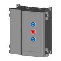
7. External command transmitters
If you connect external command transmitters to terminal J1 of
the control, the following variants are provided:
Fig.
Connection to J1 for external three-button keys.
Remove jumper J1.1/2.
Remove the jumper at J1.1/2 and set menu item 51 to the
value1.
Fig.
Connection to J1 for key switch OPEN-CLOSE.
Set menu item51 to the value0 (default setting).
Fig.
Connection to J1 for external pulse generators with an
OPEN-STOP-CLOSE switching sequence
Set menu item51 to2.
CAUTION
Crush hazard and risk of being struck by the
closing door
Persons can be struck when the door is closed
or collide with the door.
• Mount external pulse transmitters always
within the range of view of the door.
• The door must be visible from the place of
operation.
NOTICE
Dead man mode only with key switch
Dead man mode only with key switch for access
by non-instructed persons
8. Photoelectric sensor
Connect the photoelectric sensor as specified for the following
variants:
Fig.
2-wire photoelectric sensor LS2
Fig.
4-wire photoelectric sensor LS5 with testing
Fig.
Reflection light barrier
Then select the corresponding photoelectric sensor under menu
item36.
If you have selected the value3 "Photoelectric sensor mounted in
the frame", the next CLOSE run executed by the control is a
"learning cycle" for detecting the position.
This learning cycle is indicated by the valueE10 in the LED dis-
play.
NOTICE
Do not interrupt the learning cycle
The learning cycle must not be interrupted, so
that no incorrect position is recorded.
9. Door connection box
Fig.
The door connection box allows for the connection of a
safety edge, a wicket door contact and slack rope switches. The
wicket door contact and the slack rope switches are electrically
connected in series and are monitored by the control. If a wicket
door is available, the wicket door contact (Entrysense 6k8 model)
is connected to the door connection box. For this purpose, re-
move the 2kOhm resistor from the door connection box, to which
the Entrysense is clamped, and connect it there. The Entrysense
is tested in compliance with PLC as per EN13849-1 and is mon-
itored by the door control.
As slack rope switches, switches with forced actuation complying
with the specifications of EN60947-5-1, AnnexK are to be used.
The supply line of the door connection box is to be laid at the
door leaf, well protected against damage. With pulsed operation,
connect a closing edge safety device and select the correspond-
ing setting in menu item 35. Pressing the Prog button in
menu item35 for a longer time displays the measured resistance
value of the 8k2 closing edge. Example: Value 82 means 8k2.
Pressing the Prog button briefly will interrupt the display.
CAUTION
Crush hazard and risk of being struck by the
closing door
The pressure wave switches may only be actu-
ated after having been tested.
• For this purpose, select the value2 in menu
item35.
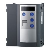
10. Radio receiver
For the use of a hand-held transmitter, attach the receiver module
(option) to J5 (Fig.
) and connect the antenna to J4. In order to
program the hand-held transmitters, follow the instructions
provided in Programming a radio hand-held transmitter in the
Programming chapter.
11. Relay outputs
Fig.
The control provides a change-over contact, max.:
250VAC / 2A or 24VDC / 1A.
The 24V output at terminalX4 may be loaded with a maximum of
150mA.
Select the desired relay function in menu item45.
 Loading...