EN-17T75 DES
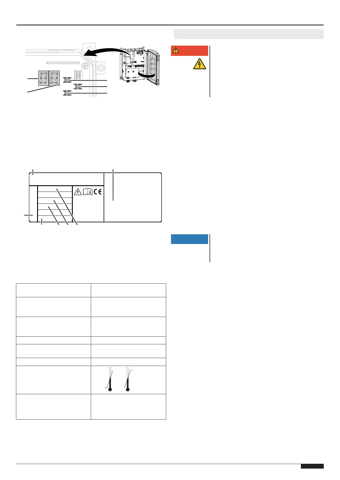
Programming control elements
1 LED display 3 Up navigation button
2 LED spot (confirmation
of the programming
entry)
4 Programming button (Prog
button)
5 Down navigation button
Rating plate
The rating plate is located at the side on the control housing. Ob-
serve the power supply specifications.
Made in Germany
WN XXXXXX XX/XX
1 Control type 5 Max. motor power
2 Manufacturer and address 6 Protection type
3 Supply voltage 7 WN number
4 Amperage
Technical data
Heightx widthx depth 250mmx 215mmx 120mm
Assembled vertically
Cable feed-throughs 6 x M20
2 x M16
2 x M20 V cutout
Supply voltage 3 N~ 400V
3~ 230V
1 N~ 230V
Control voltage 24V DC
Max. motor power Max. 0.6kW with 230V AC
Max. 1.1kW with 400V AC
Protection type IP54
Operating temperature
Manufacturer Novoferm tormatic GmbH
Eisenhüttenweg 6
D-44145 Dortmund
www.tormatic.de
4 Installation
DANGER
Hazardous voltage
The product runs on high voltage Before starting
with the installation,observe the following:
• Have all work on electrical connections car-
ried out by a skilled electrician.
• The power connection must be executed in
compliance with the mains voltage avail-
able.
Follow the instructions as well as the illustrations in the
"Connection diagrams" chapter.
1. Tools required
For the assembly of the control, you require the following tools:
• wooden folding rule or tape measure
• wrench SW13
• cross-tip screwdriver Phillips; size2
• drilling machine
• drill 6mm
• Torx screwdriver, sizeT20
• slotted screwdriver for electricians
• spirit level
• marking pencil
2. Opening the control cover
Open the housing cover by either loosening the two screws on
the left or right on the cover.
3. Assembly of the control
Assemble the control as specified on the drilling drawing.
NOTICE
Selection of the place of installation
When selecting the place of installation, observe
the preconditions in compliance with the tech-
nical data.
4. Terminal designation
J1 Start / pulse input (OPEN / STOP / CLOSE
J2 Photoelectric safety barrier 2- or 4-wire
J3 Closing edge safety device OSE / 8K2 / DW, slack rope
switch, wicket door contact
J4 Antenna
J5 Connection of radio receiver
J6 No function
J7 No function
J8 Control buttons
J9 Digital limit switch - motor cable
J11 No function
X1 Power connection
X2 Door drive
X3 Potential-free relay contact 1, door status relay
X4 24V DC, max. 150mA
 Loading...