EN-21T75 DES
Functional force monitoring check
Upon completion of the force measurement process, carry out a
functional check of the force monitoring function. Install the test
weight on the door again for this purpose. The drive must switch
off!
NOTICE
Force monitoring has not tripped during the
functional check
If the force monitoring function has not tripped,
the settings in menu item48 must be checked.
The force measurement process must be re-
peated.
Duty cycle (menu item49)
The duty cycle set prevents the drive motor from being over-
heated and avoids damage.
NOTICE
Motor5.24 with a plastic gearbox
When motor5.24 with a plastic gearbox is used,
the duty cycle must be set to the value1 (3~) or
2 (WS,1~).
Menu6 Radio settings
Programming the hand-held radio transmitter
Please observe that every hand-held transmitter must be pro-
grammed individually.
You are provided with the possibility of programming 20KeeLoq
radio codes
The following encryption types can be programmed: KeeLoq,
12 Bit Multibit. The first code programmed determines the encryp-
tion type.
Start pulse (menu item60)
1. Select "Program hand-held transmitter start button" in menu
item60.
2. Actuate the button of the hand-held transmitter for opening
the door.
ð When the code has been programmed, the dot display
on the LED display blinks 5times.
3. Go to Exit to complete the setting process.
Light function (menu item62)
Select menu item62 and actuate the light function button of the
hand-held transmitter. When the code has been programmed, the
dot display on the display blinks 5times.
Deleting radio codes (menu item63)
To delete all codes programmed, proceed as follows:
1. Select menu item63.
2. Press and hold the button for 5seconds.
When all codes have been deleted, the dot display on
the display blinks 5times.
Test run
When programming has been completed, carry out a test run by
executing all operating functions. When all operating functions
have been executed correctly, the connected door system is
ready for operation.
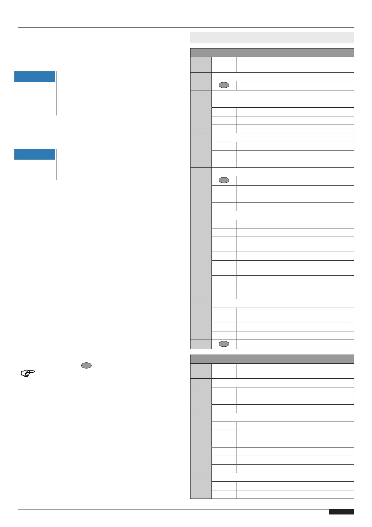
6 Program overview
Menu3 Basic settings
Menu
item
Entry Selection
30 Door setting of upper end position
Reversal of the direction (press for 5s)
31 Door setting of lower end position
33 Fine correction of upper end position
50 Factory settings
50 - 0 0...80mm lower
50 - 99 0...80mm higher
34 Fine correction of lower end position
50 Factory settings
50 - 0 0...80 mm lower
50 - 99 0...80mm higher
35 Selection of closing edge safety device
Measurement display (press 5seconds)
0 Optical closing edge safety device OSE
1 Electrical safety edge8K2 (default setting)
2 Pressure wave switch with testing
36 Selection of photoelectric sensor
0 Without photoelectric sensor (default setting)
1 2-wire photoelectric sensorLS2
2 4-wire photoelectric sensorLS5 photoelectric
reflection sensor
3 Photoelectric sensorLS2, mounted in frame
4 Photoelectric sensorLS5 photoelectric reflec-
tion sensor mounted in frame
5 4-wire photoelectric sensor with testing
6 4-wire photoelectric sensor in frame with test-
ing
37 Correction of pre-limit switch closing edge safety
25 Correction of pre-limit switch closing edge
safety (default setting)
25 - 0 0...50 mm lower
25 - 99 0...100 mm higher
- - Exit menu
Menu4 Further door settings
Menu
item
Entry Selection
40 Selection of operating mode
0 Dead man OPEN / dead man CLOSE
1 Pulse OPEN / dead man CLOSE
2 Pulse OPEN / pulse CLOSE (default setting)
45 Status relayX3
0 Door close signal
1 Door open signal (default setting)
2 Warning during the process
3 5-minute light
4 Wipe pulse with hand transmitter
5 Wipe pulse
48 Opening force limitation
0 Off (default setting)
1-30 Entry of switch-off force
 Loading...