Reelmaster 7000- DHydraulic System Page 5 - 104
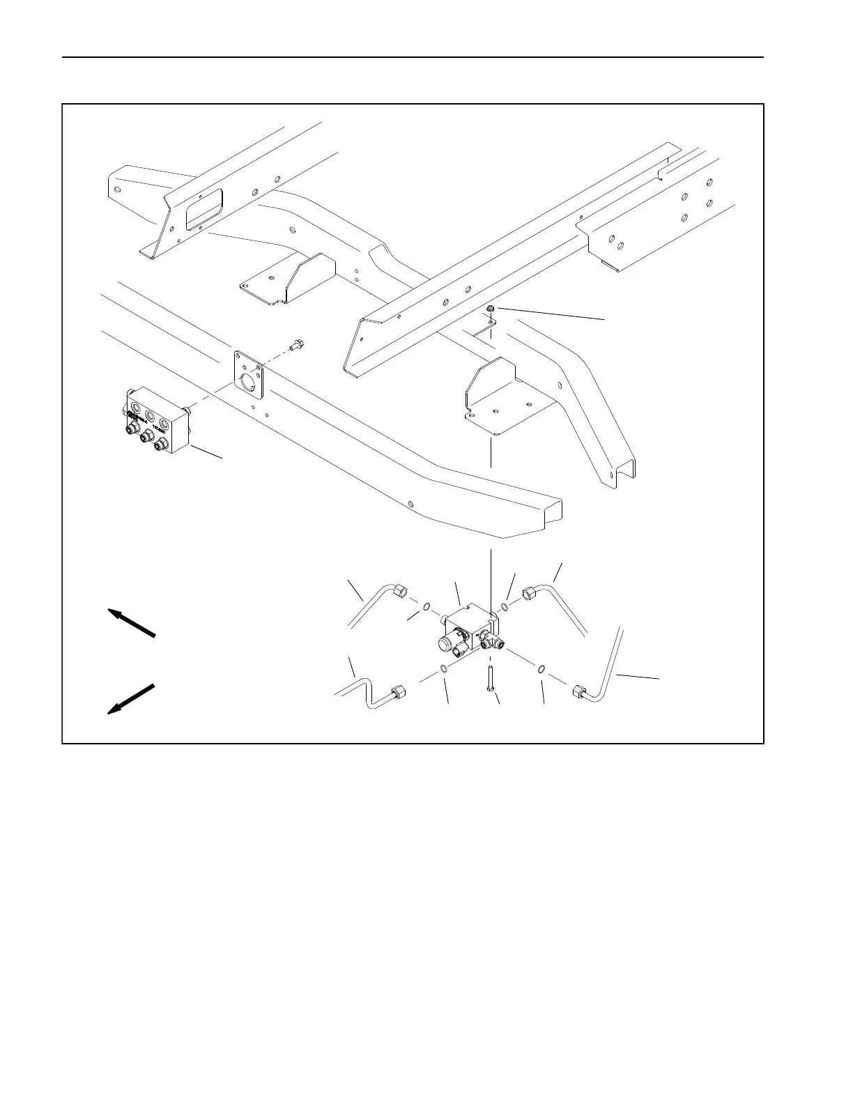
HI/LOW Range Manifold
1. HI/LOW range manifold
2. Cap screw (2)
3. Flange nut (2)
4. Lift circuit junction manifold
5. Hydraulic tube
6. O- ring (4)
7. Hydraulic tube
8. Hydraulic tube
9. Hydraulic tube
Figure 60
FRONT
RIGHT
4
2
3
5
7
6
8
9
1
6
6
6
NOTE: The ports on the HI/LOW range manifold are
marked for e asy identification of components. Refer to
the Hydraulic Schematics in Chapter 10 - Foldout Draw-
ings to identify the function of the hydraulic lines and car-
tridge valves at each port.
 Loading...


