Reelmaster 7000- DHydraulic System Page 5 - 122
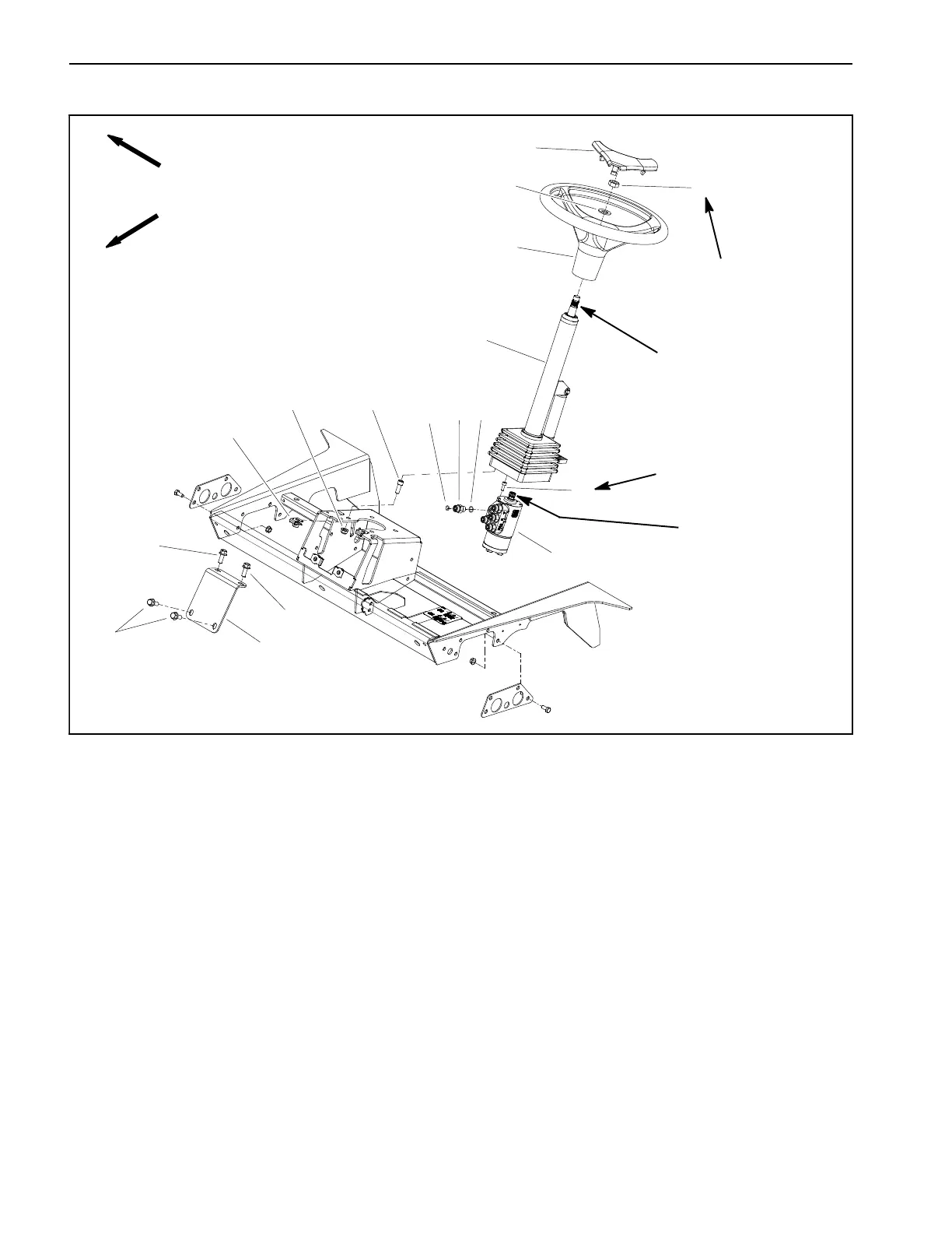
Steering Control Valve
1. Steering wheel cover
2. Lock nut
3. Steering wheel
4. Flat washer
5. O- ring
6. Flange head screw (4)
7. Steering column
8. Steering control valve
9. Socket head screw ( 4)
10. Flange nut (4)
11. Tinnerman nut (4)
12. Column brace
13. Socket head screw (4)
14. O- ring
15. Straight fitting (5)
Figure 79
FRONT
RIGHT
2
3
5
4
7
8
9
10
11
6
13
12
1
6
6
20 to 26 ft- lb
(28to35N-m)
Antiseize
Lubricant
7to10ft-lb
(10to13N-m)
14
15
Antiseize
Lubricant
Removal (Fig. 79)
1. Park machine on a level surface, lower cutting units,
stop engine, engage parking brake and remove key
from the ignition switch.
2. Remove fasteners that secure shroud to front of ma-
chine (Fig. 80). Remove shroud from machine to allow
access to steering control valve.
3. Remove four (4) flange head screws that secure col-
umn brace (item 12) to frame platform. Remove brace
from machine to allow access to steering column fasten-
ers.
4. Slide rubber bellows up from bottom of steering col-
umn. Support steering column to prevent it from falling.
5. Read the General Precautions for Removing and
Installing Hydraulic System Components at the begin-
ning of this chapter.
6. Thoroughly clean hydraulic connections prior to
loosening hydraulic lines.
7. Label all hydraulic connections for assembly pur-
poses. Note port designations on steering control valve
(Fig. 81).
 Loading...


