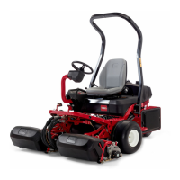
Greensmaster 3250--D
DPA Cutting Units
Page 7 -- 31
NOTE: Special tool TOR4105 (see Special Tools) can
be used instead of washers and spacer when installing
bearings and seals in roller.
2. Positionanewbearing,blackassemblywasher(see
SpecialTools)andoriginallocknutontoeachend ofthe
roller shaft (Fig. 31).
3. Tighten nuts until the bearings are seated into each
end of the roller.
4. Remove nut and black assembly washer from each
end of the roller.
IMPORTANT: Failure to grease bearing lock nut be-
fore seal installation may result in seal damage.
5. Apply a coating of grease to the nut surface to pre-
vent seal damage during seal installation (Fig. 32).
6. Carefully install seals onto bearing lock nuts. Pack
the back of the seal 75 to 90% full with #2 grease (Fig.
32).
7. Installanutwithsealontoeachendoftherollershaft.
Tightennutsuntiltheybottomagainstbearings(Fig.33).
Remove nuts from roller shaft.
8. Position an assembly spacer and yellow assembly
washer (see Special Tools) on each end of roller shaft
(Fig. 34). Thread nut onto each end of shaft.
9. Tighten each nut until the yellow assembly washers
bottomoutagainsttherollerhousing.Remove nuts, as-
sembly washers and assembly spacers from roller
shaft.
10.Lubricate lips of installed seals with #2 grease.
11.Carefully slide a dry V--ring onto each bearing lock
nut.TheV--ringsshouldbeinstalledwithoutanylubrica-
tion.
NOTE: If original bearing lock nut(s) are being used,
apply Loctite #242 (or equivalent) to threads of lock
nut(s).
12.Install bearing lock nut with V--ring onto each end of
the roller shaft. Torque lock nuts from 25 to 30 ft--lb (34
to 41 N--m).
1. Bearing lock nut
2. Seal
3. Grease nut surface
4. Pack with grease
Figure 32
3
4
2
1
1. Bearing lock nut 2. Seal
Figure 33
2
1
1. Bearing lock nut
2. Yellow assembly washer
3. Assembly spacer
4. Seal
Figure 34
3
4
2
1
DPA Cutting
Units

 Loading...