ProductOverview
g314194
g366357
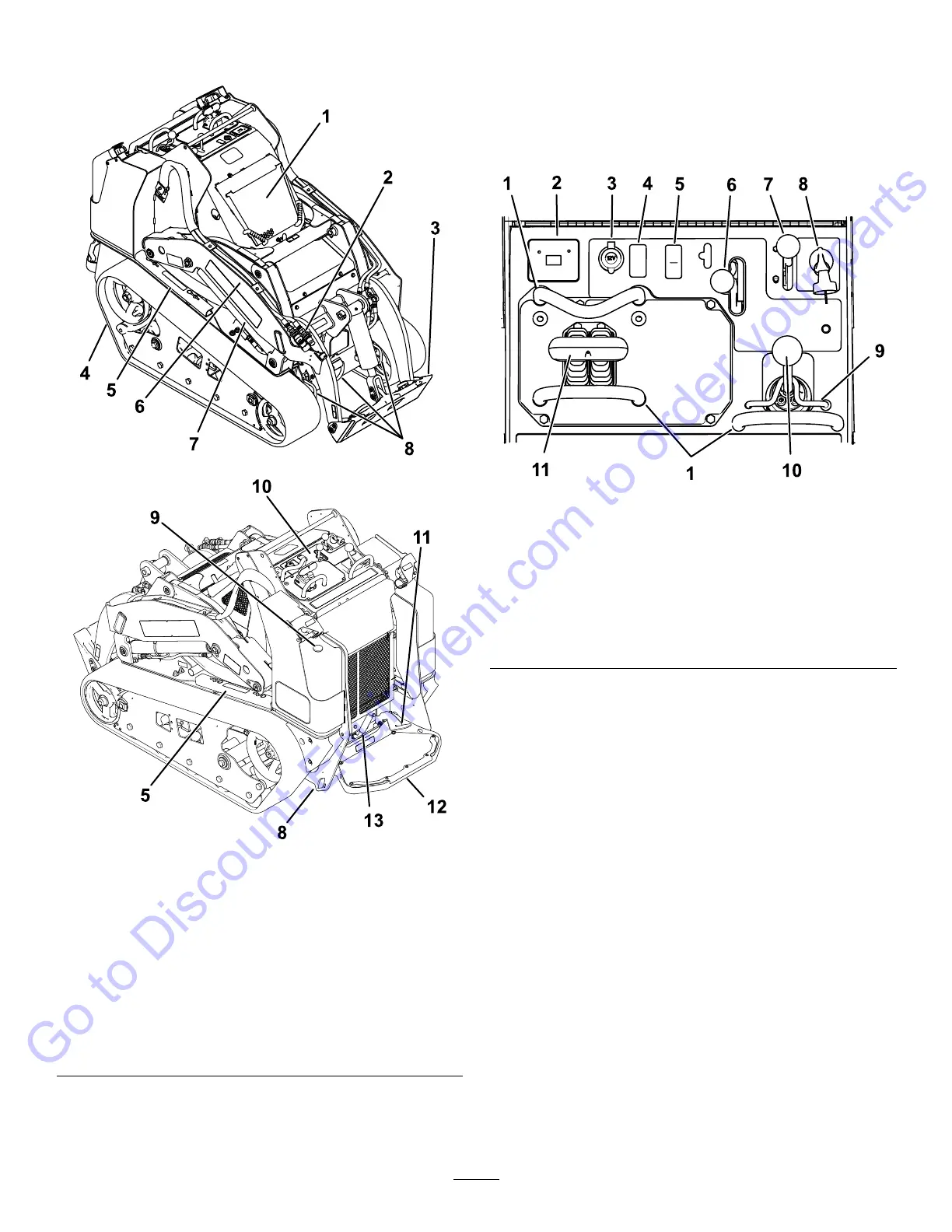
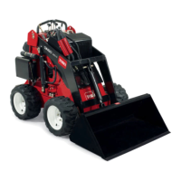
Figure3
1.Hood8.Tie-downpoint
2.Auxiliaryhydraulic
couplers
9.Fuelgauge
3.Mountplate
10.Controlpanel
4.Track11.Auxiliary-hydraulicslock
pedal
5.Cylinderlock12.Operatorplatform
6.Loaderarm13.Parkingbrake
7.Liftcylinder
Controls
Becomefamiliarwithallthecontrols(Figure4)before
youstarttheengineandoperatethetractionunit.
ControlPanel
g337136
Figure4
1.Referencebar
7.Throttlelever
2.Messagedisplay8.Keyswitch
3.Powersocket9.Loaderlock
4.Plug
10.Loader-arm/attachment-tilt
lever
5.Traction-enableswitch11.Tractioncontrol
6.Auxiliaryhydraulicslever
KeySwitch
Thekeyswitch,usedtostartandshutofftheengine,
has3positions:OFF,RUN,andSTART.Referto
StartingtheEngine(page19).
ThrottleLever
Movethecontrolforwardtoincreasetheenginespeed
andrearwardtodecreasespeed.
ReferenceBar
Whendrivingthetractionunit,usethereferencebar
asahandleandaleveragepointforcontrollingthe
tractioncontrolandtheauxiliary-hydraulicslever.To
ensuresmooth,controlledoperation,donottake
yourhandsoffthereferencebarswhileoperatingthe
machine.
10
Go to Discount-Equipment.com to order your parts