6.Movethemotioncontrolleverforwardandreverse,
thenbacktoneutral.Thewheelmuststopturningor
slightlycreepinreverse.
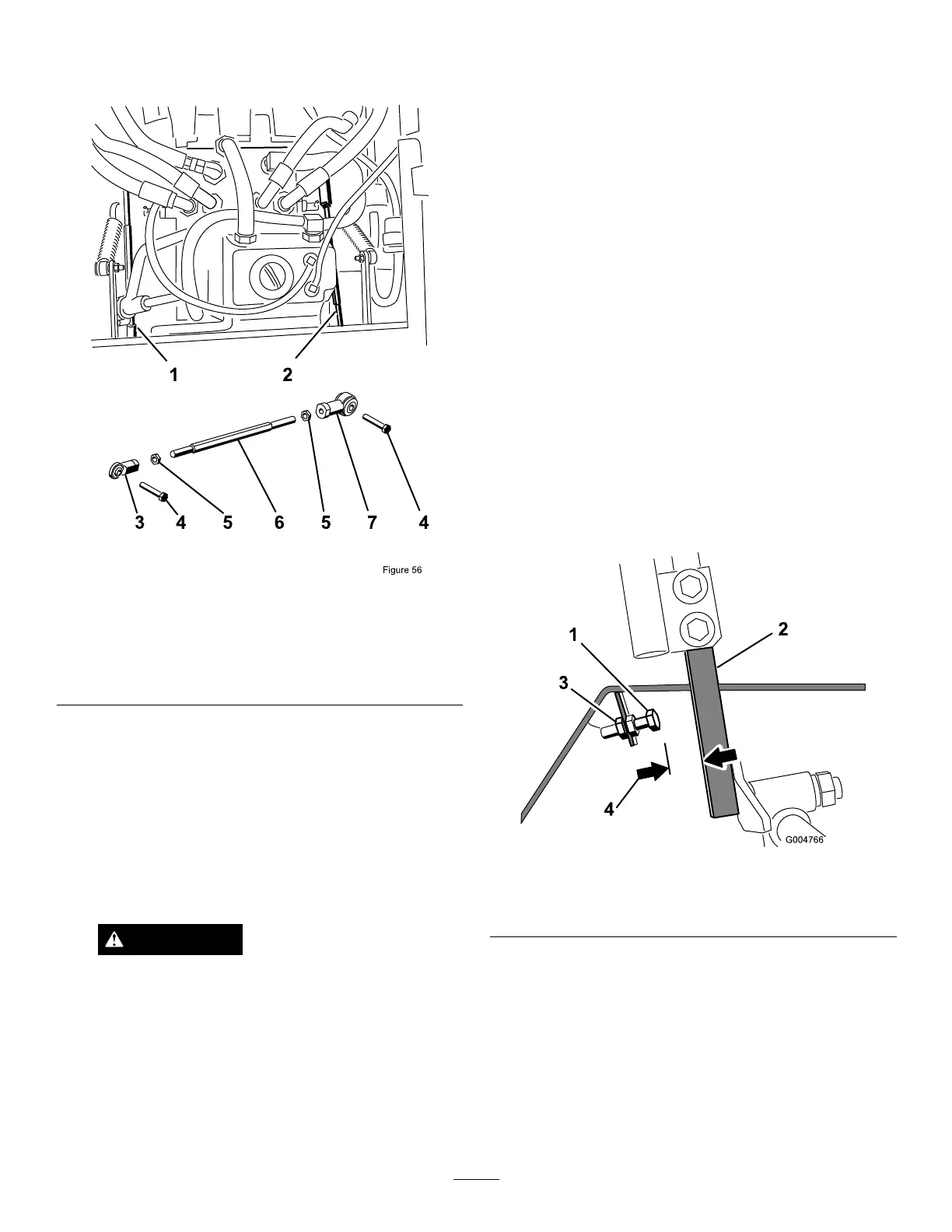
Figure72
1.Rightpumprod5.JamNut
2.Leftpumprod6.Hexshaft
3.Balljoint7.Balljoint
4.Bolt
7.MovethethrottlelevertotheFastposition.Makesure
wheelremainsstoppedorslightlycreepsinreverse,
adjustifnecessary.
8.Repeatsteps5through7fortheotherside.
9.Tightenthejamnutsattheballjoints(Figure70).
10.MovethethrottlelevertotheSlowpositionandstop
theengine.
11.Removethejumperwirefromthewireharness
connectorandplugtheconnectorintotheseatswitch.
WARNING
Electricalsystemwillnotperformproper
safetyshutoffwithjumperwireinstalled.
•Removejumperwirefromwireharness
connectorandplugconnectorintoseat
switchwhenadjustmentiscompleted.
•Neveroperatethisunitwithjumper
installedandseatswitchbypassed.
12.Lowertheseat.
13.Removethejackstands.
AdjustingtheMaximum
GroundSpeed
Note:Ifyouwishtoreducethemaximummachinespeed,
setthespeedforbothcontrolleversasdirectedbelow,then
backeachstopboltoutanequalamounttowardthecontrol
leveruntilyoureachthemaximumspeedyoudesire(youwill
likelyhavetotestyouradjustmentseveraltimes).Ensurethat
themachinedrivesstraightanddoesnotturnwhenboth
controlleversarepushedallthewayforward.Ifthemachine
turns,youdonothavethestopboltsevenlysetandwillneed
toadjustthemfurther.
1.DisengagethePTO,movethemotioncontrolleversto
theneutrallockedpositionandsettheparkingbrake.
2.MovethethrottlelevertotheSlowposition,stopthe
engine,removethekey,andwaitforallmovingpartsto
stopbeforeleavingtheoperatingposition.
3.Unlatchtheseatandpivotitforward.
Note:Ifadditionalaccessisrequiredundertheseat,
thesidepanelsmayberemoved.
4.Loosenthejamnutonthestopboltforoneofthe
controllevers(Figure73).
Figure73
1.Stopbolt
3.Jamnut
2.Controllever4.1.5mm(0.060inch)
5.Threadthestopboltallthewayin(awayfromthe
controllever).
6.Pushthecontrolleverallthewayforwarduntilitstops
andholditthere.
7.Threadthestopboltout(towardsthecontrollever)
untilthereisagapof1.5mm(0.060inch)betweenthe
headofthestopboltandthecontrollever.
8.Tightenthejamnuttosecurethestopboltinplace.
9.Repeatsteps4through8fortheothercontrollever.
42