4
InstallingtheCuttingUnitson
theLiftArms
Partsneededforthisprocedure:
4Thrustwasher
4
Clevispin
2Hairpincotter
2
Height-of-cutcollar
2
Clevispin
2Hairpincotter
2
Bolt(1/2x3/4inch)
2Washer
Procedure
1.Movethecuttingunitintopositioninfrontofthe
tractionunit.
2.MovetheliftlevertotheFloatposition.Pushalift
armdownuntiltheholesintheliftarmlineupwith
theholesinthecastorarmbracketandtheheight
ofcutrodcanbeinsertedintotheliftarmpads
(
Figure4).
3.Securetheliftarmtothecastorarmwith2thrust
washers,aclevispinandahairpincotter.Position
thethrustwashersbetweentheliftarmandthe
castorarmbracket(
Figure4).Insertendofcotter
pinintotheslotinthecastorarmtabtoretaincotter
pin.
4.Repeattheprocedureontheoppositeliftarm.
5.Startthetractionunitandraisethecuttingunit.
6.Pushdownontherearofthecuttingunitandinsert
theheightofcutrodsthroughtheliftarmpads.
7.Installtheheightofcutcollarsontotheheightof
cutrodsandsecurewiththeclevispinsandhairpin
cotters(
Figure4).Positiontheheadoftheclevispin
towardthefrontofthedeck,ifpossible.
8.Installabolt(1/2x3/4inch)andawashertotopof
eachheightofcutrod(Figure4).
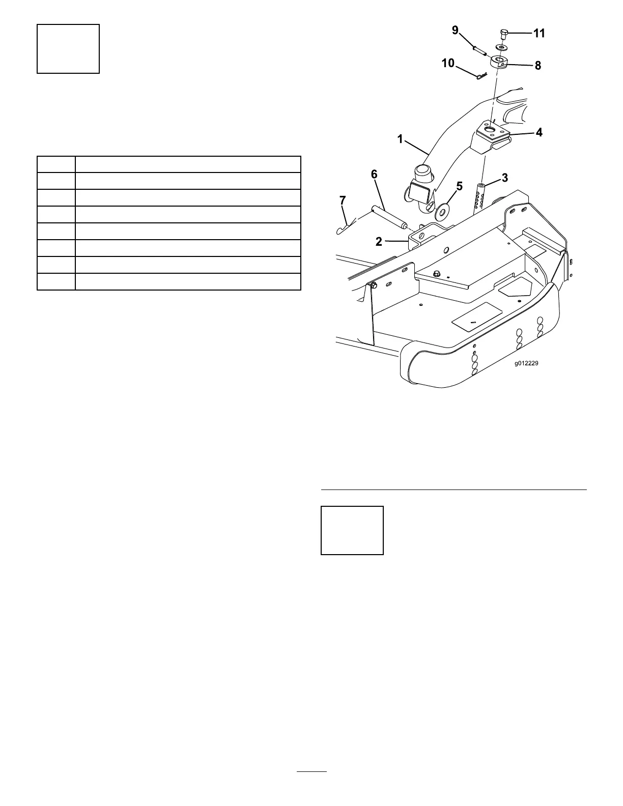
Figure4
1.Liftarm
7.Hairpincotter
2.Castorarmbracket8.Height-of-cutcollar
3.Height-of-cutrod9.Clevispin
4.Liftarmpads
10.Hairpincotter
5.Thrustwashers11.Bolt
6.Clevispin
5
ConnectingthePTOShaftto
theCuttingUnitGearBox
NoPartsRequired
Procedure
1.SlidethemalePTOshaftintothefemalePTOshaft
(Figure5).Alignthemountingholesinthegearcase
inputshaftwiththeholesinthePTOshaftandslide
themtogether.
10