•Model30303,72inchRearDischarge
•Model30304,72inchGuardian
2
InstallingtheCastorWheel
Assemblies
Partsneededforthisprocedure:
2
Castorwheelassembly
Procedure
Thethrustwashers,spacers,andtensioningcapshave
beeninstalledonthecastorwheelspindlesforshipping.
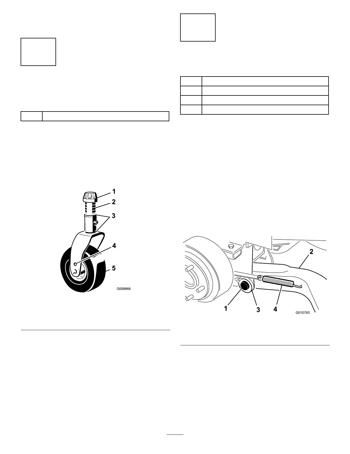
1.Removethetensioningcapsfromthespindle
shaftsandslideoffthespacersandthrustwashers
(
Figure2).
Figure2
1.Tensioningcap4.Axlemountingholes
2.Spacers5.Castorwheel
3.Thrustwashers
2.Slidethespacersontothecastorspindletogetthe
desiredheight-of-cut;referto
Figure7&Figure8
todeterminethecombinationsofspacersforthe
setting.Slideathrustwasherontothespindle,push
thecastorthroughthecastorarm.Installanother
thrustwasherandtheremainingspacersontothe
spindleandinstallthetensioningcaptosecurethe
assembly(Figure2).
Important:Thethrustwashers,notthespacers,
mustcontactthetopandbottomofthecastor
arm.
3
InstallingtheLiftArms
Partsneededforthisprocedure:
1
Liftarm,right
1
Liftarm,left
2Pivotpinassembly
2
Cotterpin
Procedure
1.Ononesideofthetractionunit,loosen(donot
remove)thewheelnutssecuringthewheelandtire
assemblytothefrontwheelstuds.
2.Jackupthemachineuntilthefrontwheelisoffof
theoor.Usejackstandsorblockthemachineto
preventitfromaccidentallyfalling.
3.Removethewheelnutsandslidethewheelandtire
assemblyoffofthestuds.
4.Mountaliftarmtothepivotbracketwithapivotpin
andacotterpin(
Figure3).Mounttheliftarmwith
thebendpositionedoutward.
Figure3
1.Pivotpin3.Pivotbracket
2.Liftarm
4.Brakereturnspring
5.Hookthebrakereturnspringintotheholeinthe
liftarm(Figure3).
6.Installthewheelandtireassembly.Torquethewheel
nutsto75–80ft-lb(102–108N-m).
7.Repeattheprocedureontheoppositesideofthe
machine.
9