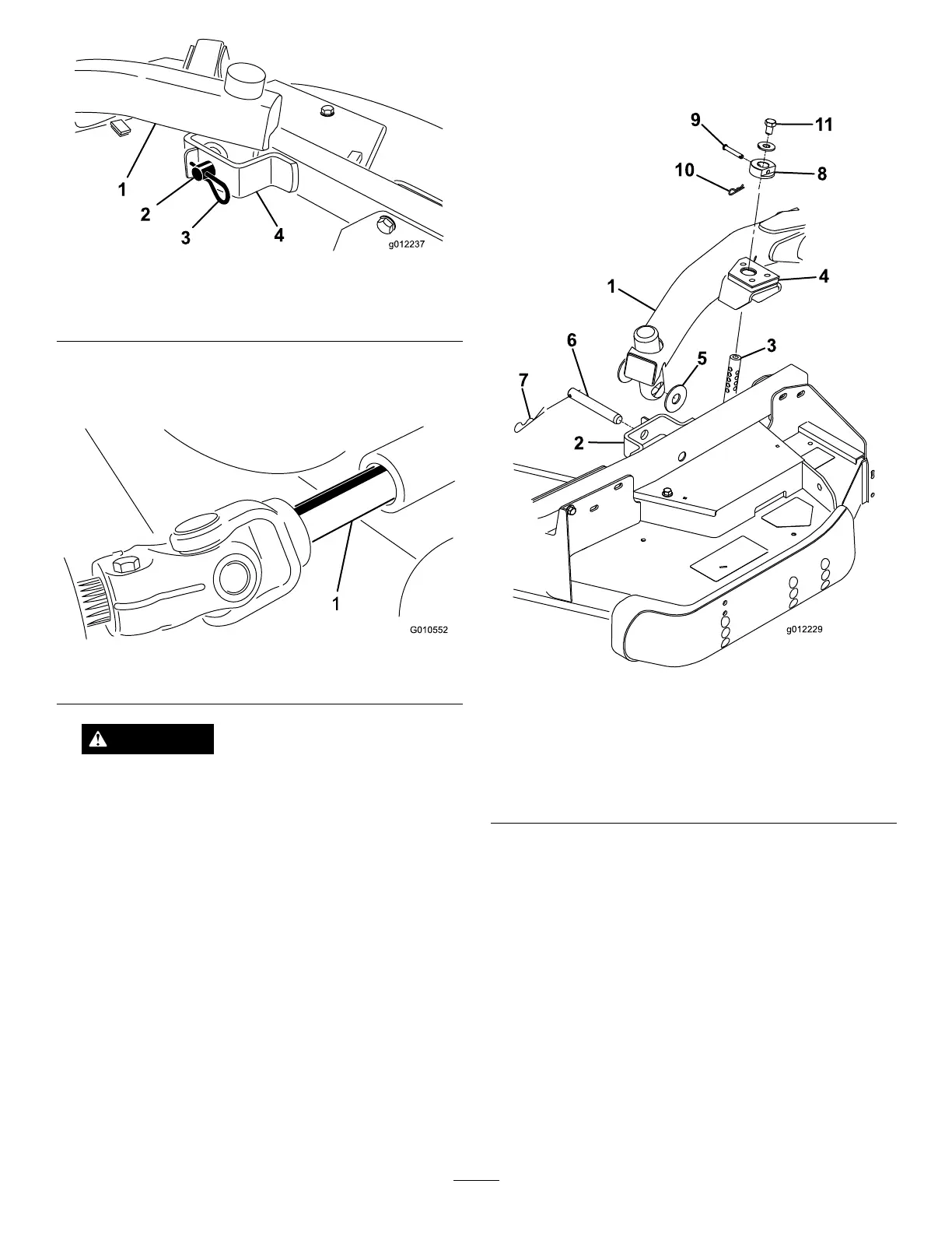
Figure21
1.Liftarm
3.Hairpincotter
2.Clevispin4.Castorarmbracket
5.Rollthecuttingunitawayfromthetractionunit,
separatingthemaleandfemalesectionsofthePTO
shaft(Figure22).
Figure22
1.PTOshaft
DANGER
IftheengineisstartedandthePTOshaftis
allowedtorotate,seriousinjurycouldresult.
DonotstarttheengineandengagethePTO
leverwhenthePTOshaftisnotconnectedto
thegearboxonthecuttingunit.
MountingtheCuttingUnitto
theTractionUnit
1.Positionthemachineonalevelsurfaceandshutthe
engineoff.
2.Movethecuttingunitintopositioninfrontofthe
tractionunit.
3.SlidethemalePTOshaftintothefemalePTOshaft
(Figure22).
4.MovetheliftlevertotheFloatposition.Pushalift
armdownuntiltheholesintheliftarmlineupwith
theholesinthecastorarmbracketandtheheight
ofcutrodcanbeinsertedintotheliftarmpads
(Figure23).
Figure23
1.Liftarm
7.Hairpincotter
2.Castorarmbracket8.Height-of-cutcollar
3.Height-of-cutrod9.Clevispin
4.Liftarmpads
10.Hairpincotter
5.Thrustwashers11.Bolt
6.Clevispin
5.Securetheliftarmtothecastorarmwith(2)thrust
washers,aclevispinandahairpincotter.Position
thethrustwashersbetweentheliftarmandthe
castorarmbracket(Figure23).Insertendofcotter
pinintotheslotinthecastorarmtabtoretaincotter
pin.
6.Repeattheprocedureontheoppositeliftarm.
7.Startthetractionunitandraisethecuttingunit.
8.Pushdownontherearofthecuttingunitandinsert
theheightofcutrodsthroughtheliftarmpads.
9.Installtheheightofcutcollarsontotheheightof
cutrodsandsecurewiththeclevispinsandhair
19