1.Parkthemachineonalevelsurface.
2.Starttheengineandraisethecuttingunitsto
changeheightofcut.
3.Shutofftheengine,engagetheparkingbrake,
andremovethekeyfromtheignitionafterthe
cuttingunitisraised.
4.Positionthecaster-wheelaxlesinthesame
holesinallcasterforks.
g008866
Figure20
1.Tensioningcap4.Topaxle-mountinghole
2.Spacers5.Casterwheel
3.Shims
Note:Whenoperatingin64mm(2-1/2inch)
heightofcutorhigher,installtheaxleboltinthe
lowercaster-forkholetopreventgrassbuildup
betweenthewheelandthefork.Whenoperating
atheightsofcutslowerthan64mm(2-1/2
inches)andgrassbuildupisdetected,reverse
themachinesdirectiontopullanyclippings
awayfromthewheel/forkarea.
5.Removethetensioningcapfromthespindle
shaftandslidethespindleoutofthecasterarm
(Figure20).
6.Install2shimsontothespindleshaftasthey
wereoriginallyinstalled.
Note:Theseshimsrequirealevelacross
theentirewidthofthecuttingunits.Slidethe
appropriatenumberof13mm(1/2inch)spacers
(refertothechartbelow)ontothespindleshaft
toattainthedesiredheightofcut;thenslidethe
washerontotheshaft.
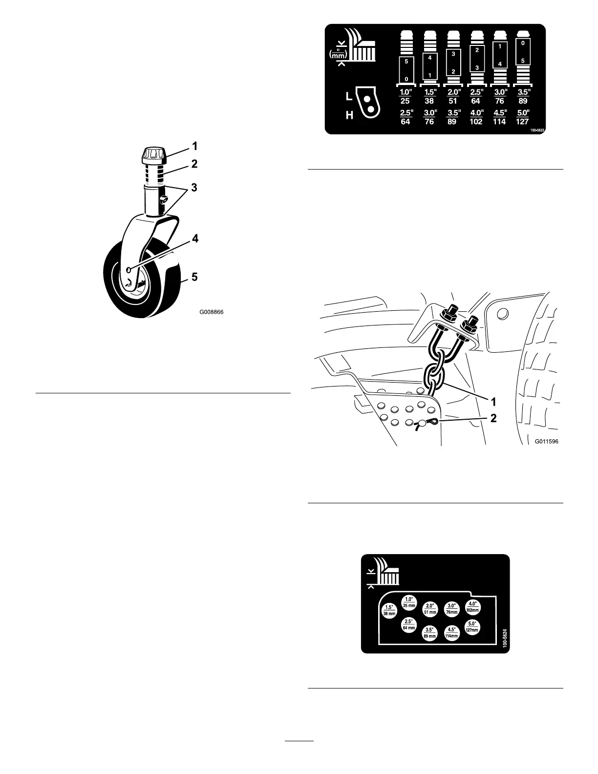
Refertothefollowingcharttodeterminethe
combinationsofspacersforthesetting(Figure
21):
decal100-5622nc
Figure21
7.Pushthecasterspindlethroughthefrontcaster
armandinstalltheshims(astheywereoriginally
installed)andtheremainingspacersontothe
spindleshaft.
8.Installthetensioningcaptosecuretheassembly.
9.Removethehairpincotterandclevispin
securingtheheight-of-cutchainstotherearof
thecuttingunit(Figure22).
g011596
Figure22
1.Height-of-cutchain2.Clevispinandhairpin
cotter
10.Mounttheheight-of-cutchainstothedesired
height-of-cutholewiththeclevispinandhairpin
cotter(Figure23).
decal100-5624nc
Figure23
26