Note:Whenusing25mm(1inch),38mm(1-1/2
inches),or51mm(2inches)heightsofcut,movethe
skidsandgaugewheelstothehighestposition.
SideCuttingUnits
Toadjusttheheightofcutonthesidecuttingunits,
addorremoveanequalnumberofspacersfromthe
casterforks,positionthecaster-wheelaxlesinthe
highorlowheight-of-cutholesinthecasterforks,and
securethepivotarmstotheselectedheight-of-cut
bracketholes.
1.Positionthecaster-wheelaxlesinthesame
holesinallofthecasterforks(Figure24and
Figure26).
2.Removethetensioningcapfromthespindle
shaftandslidethespindleoutofthecasterarm
(Figure24).
g008866
Figure24
1.Tensioningcap4.Topaxle-mountinghole
2.Spacers5.Casterwheel
3.Shims3mm(1/8inch)
3.Install2shimsontothespindleshaftasthey
wereoriginallyinstalled.Theseshimsare
requiredtoachievealevelacrosstheentire
widthofthecuttingunits.Slidetheappropriate
numberof13mm(1/2inch)spacersontothe
spindleshafttogetthedesiredheight-of-cut;
thenslidethewasherontotheshaft.
Note:Theseshimsrequirealevelacross
theentirewidthofthecuttingunits.Slidethe
appropriatenumberof13mm(1/2inch)spacers
(refertothechartbelow)ontothespindleshaft
toattainthedesiredheightofcut;thenslidethe
washerontotheshaft.
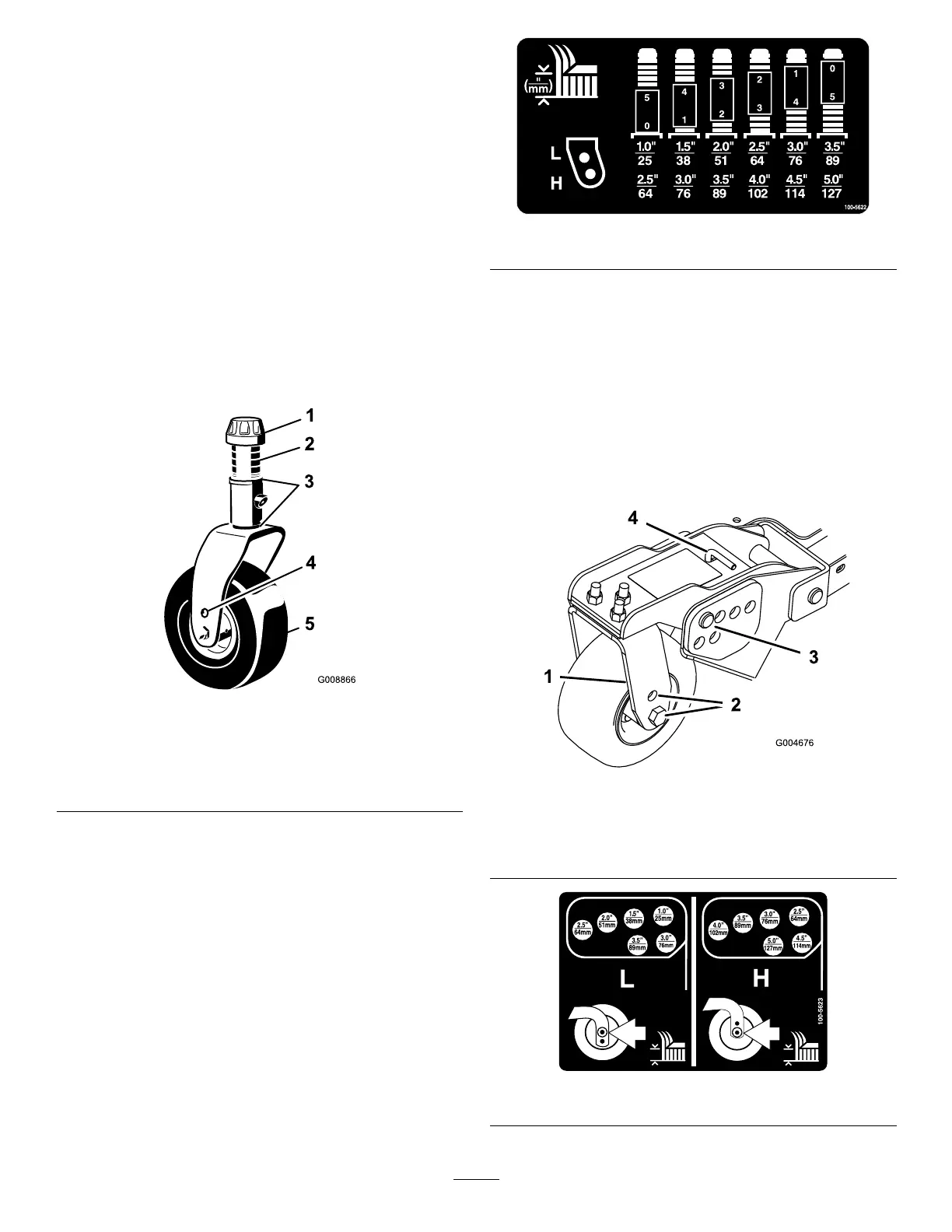
Refertothefollowingcharttodeterminethe
combinationsofspacersforthesetting(Figure
25).
decal100-5622nc
Figure25
4.Pushthecasterspindlethroughthefrontcaster
armandinstalltheshims(astheywereoriginally
installed)andtheremainingspacersontothe
spindleshaft.
5.Removethehairpincotterandclevispinsfrom
thecaster-pivotarms(Figure26).
6.Rotatethetensionrodtoraiseorlowerthepivot
armuntiltheholesarealignedwiththeselected
height-of-cutbracketholesinthemower-deck
frame(Figure26andFigure27).
g004676
Figure26
1.Caster-pivotarm3.Clevispinandhairpin
cotter
2.Axle-mountingholes4.Tensionrod
decal100-5623nc
Figure27
27