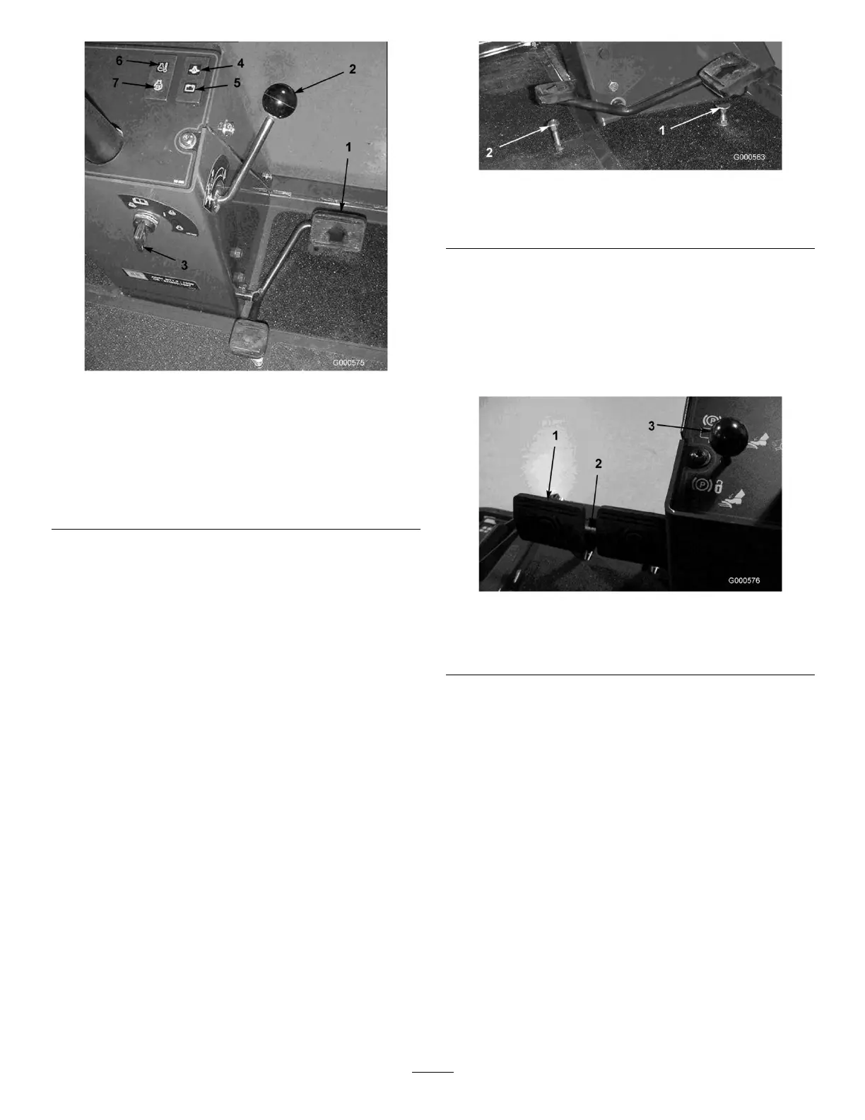
Figure5
1.Tractionpedal
5.Chargeindicator
2.Forwardspeedcontrol6.Enginecoolant
temperaturewarning
light
3.Keyswitch
7.Glowplugindicatorlight
4.Engineoilpressure
warninglight
ChargeIndicator
Thechargeindicator(Figure5)illuminateswhenthe
systemchargingcircuitmalfunctions.
EngineCoolantTemperatureWarning
Light
Thelight(Figure5)illuminatesandtheengineshuts
downwhencoolantreachesanexcessivelyhigh
temperature.
GlowPlugIndicatorLight
Whenlit,theglowplugindicatorlight(Figure5)
indicatesthattheglowplugsareon.
SpeedLimiterScrews
Adjustthescrew(s)(Figure6)tolimittheamountthe
tractionpedalcanbedepressedintheforwardorreverse
directiontolimitspeed.
Important:Thespeedlimiterscrewmuststopthe
tractionpedalbeforethepumpreachesfullstroke
ordamagetothepumpmayoccur.
Figure6
1.Forwardspeedlimiter
screw
2.Reversespeedlimiter
screw
BrakePedals
Twofootpedals(Figure7)operateindividualwheel
brakesforturningassistance,parking,andtoaidin
obtainingbettersidehilltraction.Alatchconnectsthe
pedalsforparkingbrakeoperationandtransport.
Figure7
1.Brakepedals3.Parkingbrakelatch
2.Pedallockinglatch
PedalLockingLatch
Thepedallockinglatch(Figure7)connectsthepedals
togethertoengagetheparkingbrake.
ParkingBrakeLatch
Aknobontheleftsideoftheconsoleactuatesthe
parkingbrakelock(Figure7).Toengagetheparking
brake,connectthepedalswiththelockinglatch,push
downonbothpedals,andpulltheparkingbrakelatch
out.Toreleasetheparkingbrake,depressbothpedals
untiltheparkingbrakelatchretracts.
ThrottleControl
Movethecontrol(Figure8orFigure9)forwardto
increasetheenginespeedandrearwardtodecreasethe
speed.
16