3.Lubricatethenewltergasketandllthelterwith
hydraulicuid.
Figure56
1.Hydrauliclter
Figure57
1.Hydrauliclter
4.Ensurethattheltermountingareaisclean.Screw
thelteronuntilthegasketcontactsthemounting
plate;thentightenthelteranadditional1/2turn.
5.Starttheengineandletitrunforabouttwominutes
topurgeairfromthesystem.Stoptheengineand
checkforleaks.
CheckingtheHydraulicLines
andHoses
ServiceInterval:Beforeeachuseordaily
Inspectthehydrauliclinesandhosesdailyfor
leaks,kinkedlines,loosemountingsupports,wear,
loosettings,weatherdeterioration,andchemical
deterioration.Makeallnecessaryrepairsbefore
operating.
Hydraulicuidescapingunderpressurecan
penetrateskinandcauseinjury.
•Makesureallhydraulicuidhosesand
linesareingoodconditionandallhydraulic
connectionsandttingsaretightbefore
applyingpressuretothehydraulicsystem.
•Keepyourbodyandhandsawayfrompin
holeleaksornozzlesthatejecthighpressure
hydraulicuid.
•Usecardboardorpapertondhydraulic
leaks.
•Safelyrelieveallpressureinthehydraulic
systembeforeperforminganyworkonthe
hydraulicsystem.
•Seekimmediatemedicalattentionifuid
isinjectedintoskin.
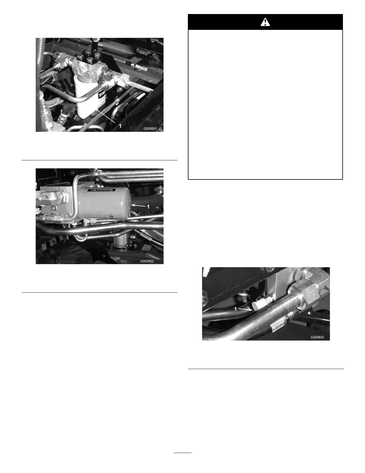
HydraulicSystemTestPorts
Thetestportsareusedtotestthepressureinthe
hydrauliccircuits.ContactyourlocalTorodistributor
forassistanceorrefertotheServiceManual.
TestPortA(Figure58),locatedonrearoflter
manifold,underrighthandframerail.Usedtomeasure
thetractionsystemchargepressure.
Figure58
1.T estportA(Charge)
TestPortB(Figure59),locatedonsideofcounter
balancemanifold,underoperatorsseat.Usedtomeasure
thecounterbalancepressureappliedtocuttingunitsfor
increasedtraction.
TestPortC(Figure59),locatedonfrontof2wheel
drive/4wheeldrivemanifoldthroughfrontaccesspanel
onoperatorplatform.Usedtomeasurethe4wheel
45