FrontCastorWheels
1.Removethetensioningcapfromthespindleshaft
(Figure7)andslidethespindleoutofthecastorarm.
Putthe2shims(1/8inch)ontothespindleshaftas
theywereoriginallyinstalled.Theseshimsarerequired
toachievealevelacrosstheentirewidthofthecutting
units.Slidetheappropriatenumberof1/2inchspacers
ontothespindleshafttogetthedesiredheight-of-cut;
thenslidethewasherontotheshaft.
RefertoFigure8todeterminethecombinationsof
spacersforthesetting.
2.Pushthecastorspindlethroughthecastorarm.Install
theshims(astheywereoriginallyinstalled)andthe
remainingspacersontothespindleshaft.Installthe
tensioningcaptosecuretheassembly.
Note:Whenusing25mm(1inch),38mm(1-1/2
inch),oroccasionally51mm(2inch)height–of–cut,
movetheskidsandrollertothehighestholes.
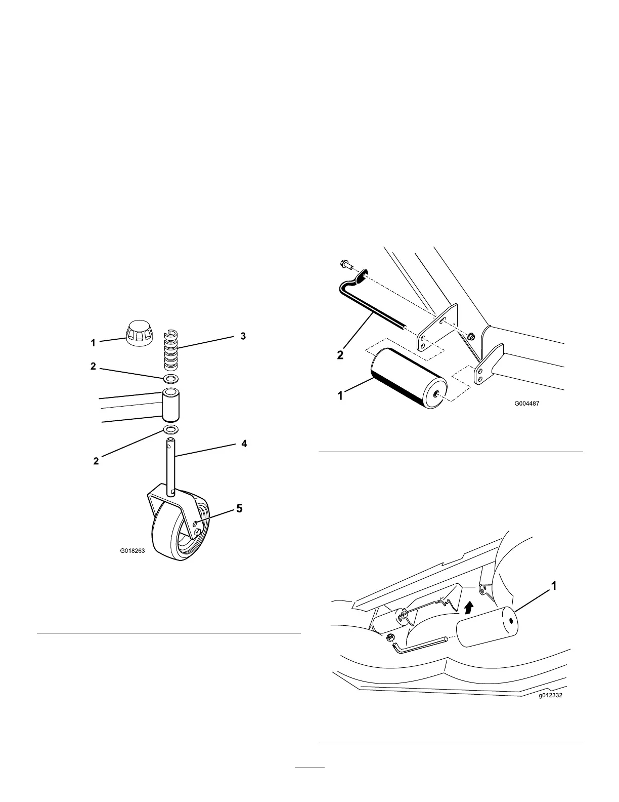
RearCastorWheels
1.Removethetensioningcapfromthespindleshaft
(Figure9).
Figure9
1.Tensioningcap
4.CastorWheel
2.Shims
5.Axlemountingholes
3.“C”Shapedspacers
Note:Therearcastorforkassemblydoesnotneed
toberemovedfromthecastorarmtochangethe
height-of-cut.
2.Removeoradd”C”shapedspacersatthenarrow
portionofthespindleshaft,belowthecastorarm,to
getthedesiredheight-of-cut.Makesurethattheshims,
notthespacers,contactthetopandbottomofthe
castorarm.
3.Installthetensioningcaptosecuretheassembly.
4.Ensurethatallfourcastorwheelsaresetatthesame
height-of-cut.
Note:Whenusing25mm(1inch),38mm(1-1/2inch),or
occasionally51mm(2inch)height–of–cut,movetheskids
androllertothehighestholes.
AdjustingtheRollers
Note:Ifthecuttingunitistobeusedinthe25or38mm(1
or1-1/2inch)height-of-cutsetting,thecuttingunitrollers
mustberepositionedinthetopbracketholes.
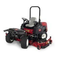
Toadjustthefrontrollers(Figure10).
1.Removethescrewandnutsecuringtherollershaftto
thedeckbracket.
Figure10
1.Roller
2.Rollershaft
2.Slidetheshaftoutofthelowerbracketholes,alignthe
rollerwiththetopholes,andinstalltheshaft.
3.Installthescrewandnuttosecuretheassemblies.
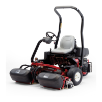
Toadjusttherear(internal)rollers(Figure11)
Figure11
1.Internalrollers
13