StoppingtheMachine
Tostopthemachine,movethetraction-controllevers
totheNEUTRALpositionandthentotheLOCKED
position,disengagethepowertakeoff(PTO),andturn
theignitionkeytotheOFFposition.
Settheparkingbrakewhenyouleavethemachine.
Remembertoremovethekeyfromtheignitionswitch.
CAUTION
Childrenorbystandersmaybeinjuredifthey
moveorattempttooperatethemachinewhile
itisunattended.
Alwaysremovetheignitionkeyandsetthe
parkingbrakewhenleavingthemachine
unattended,evenifjustforafewminutes.
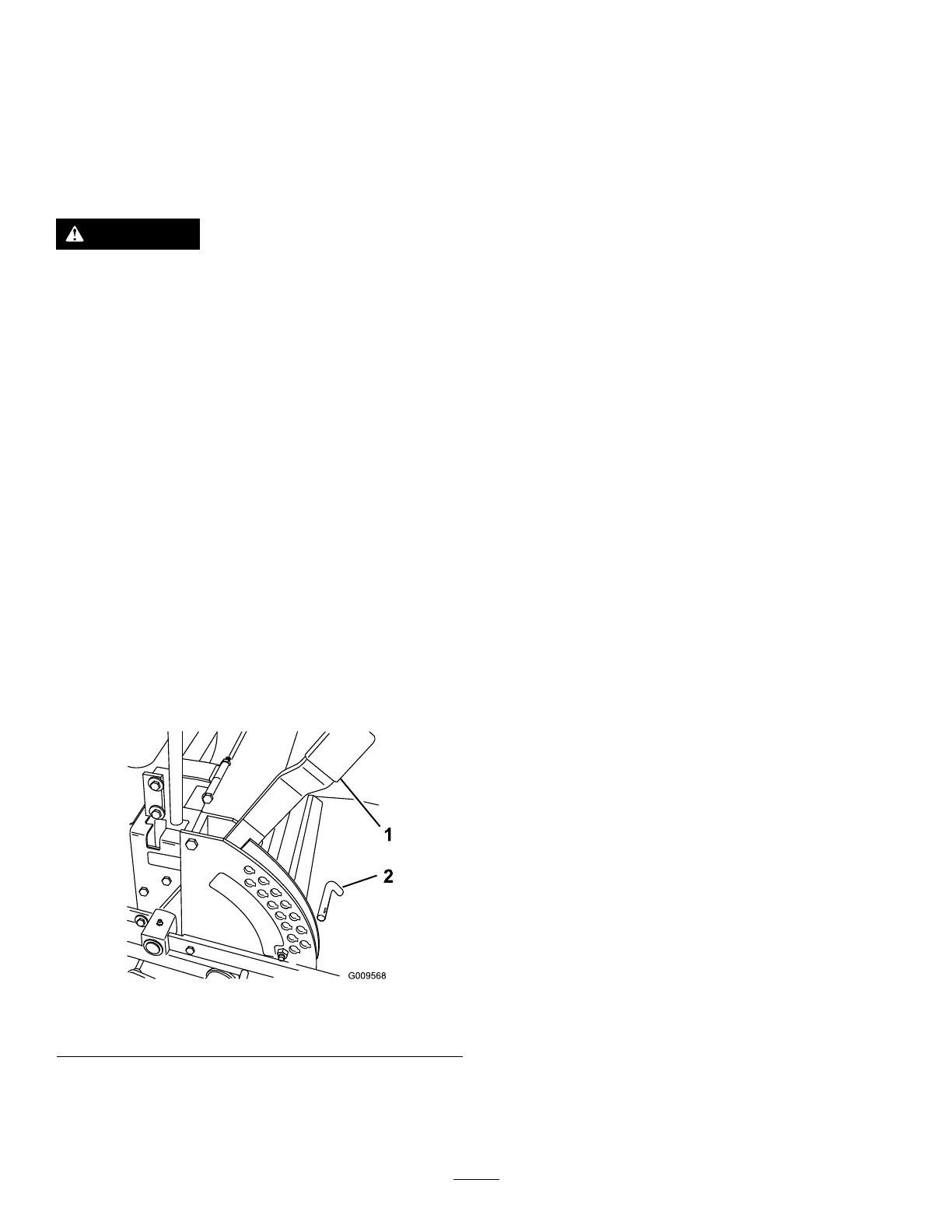
AdjustingtheHeight-of-Cut
Theheight-of-cutisadjustedfrom38to127mm
(1-1/2to5inches)in6mm(1/4inch)incrementsby
relocatingthepinintodifferentholelocations.
1.Raisetheheight-of-cutlevertotheTRANSPORT
position(alsothe127mm(5inch)cutting-height
position)(Figure18).
2.Toadjust,removethepinfromtheheight-of-cut
bracket(Figure18).
3.Selectaholeintheheight-of-cutbracket
correspondingtotheheight-of-cutdesiredand,
insertthepin(Figure18).
4.Movethelevertotheselectedheight.
g009568
Figure18
1.Height-of-cutlever
2.Pin
AdjustingtheAnti-Scalp
Rollers
Wheneveryouchangetheheight-of-cut,itis
recommendedtoadjusttheheightoftheanti-scalp
rollers.
1.DisengagethePTO,movethemotion-control
leverstotheNEUTRAL-LOCKposition,andsetthe
parkingbrake.
2.Shutofftheengine,removethekey,andwait
forallmovingpartstostopbeforeleavingthe
operatingposition.
3.Afteradjustingtheheightofcut,adjusttherollers
byremovingtheangenut,bushing,spacer,
andbolt(Figure19orFigure20).
Note:The2middlerollersdonothaveaspacer
(Figure19orFigure20).
4.Selectaholesotheanti-scalprollerispositioned
tothenearestcorrespondingheight-of-cut
desired.
5.Installtheangenutbushing,spacer,andbolt.
Torqueto54to61N∙m(40to45ft-lb)(Figure
19orFigure20).
6.Repeatthisadjustmentontheotheranti-scalp
rollers.
24