9.Applyslightrearwardpressureonthe
motion-controllever,turntheheadofthe
adjustmentboltintheappropriatedirectionuntil
thecontrolleveriscenteredintheNEUTRAL-LOCK
position(Figure67).
Note:Keeprearwardpressureontheleverto
keepthepinattheendoftheslotandtoallow
theadjustmentbolttomovethelevertothe
appropriateposition.
10.Tightenthenutandjamnut(Figure67).
11.Repeatfortheoppositesideofthemachine.
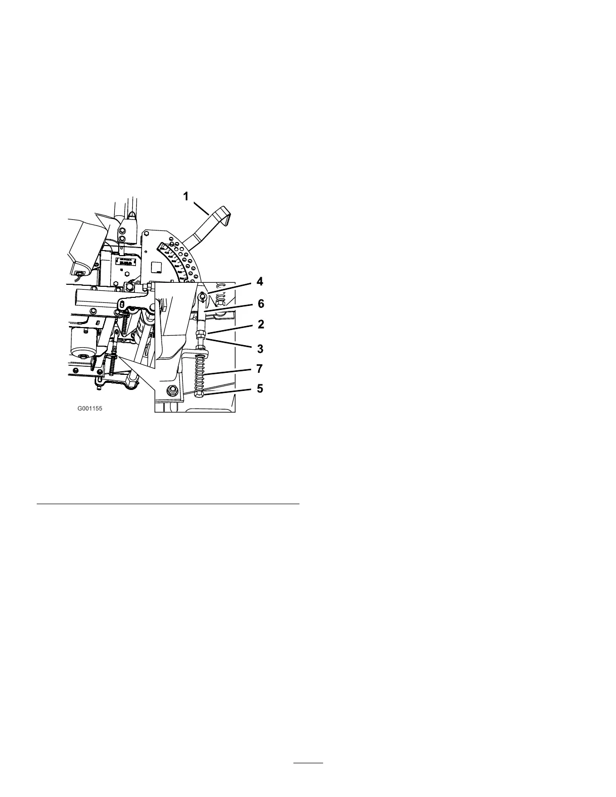
g001155
Figure67
1.Height-of-cutlever
5.Adjustmentbolt
2.Nutagainstyoke
6.Yoke
3.Jamnut
7.Spring
4.Clevispininslot
HydraulicSystem
Maintenance
ServicingtheHydraulic
System
HydraulicOilType:Toro
®
HYPR-OIL
™
500hydraulic
oilorMobil
®
115W-50oil
HydraulicSystemOilCapacity:3.9L(132oz)
Important:Useoilspecied.Otheruidscould
causesystemdamage.
CheckingtheHydraulicFluidLevel
ServiceInterval:Aftertherst8hours
Every25hours
Note:Thereare2waysofcheckingthehydraulicoil.
1iswhentheoiliswarmand1iswhentheoiliscold.
Thebafeinsidethetankhas2levelsdependingif
theoiliswarmorcold.
1.Positionthemachineonalevelsurfaceandset
theparkingbrake.
2.Cleantheareaaroundllerneckofhydraulic
tank(Figure68).
3.Removethecapfromthellerneck.Lookinside
tocheckifthereisuidinthereservoir(Figure
68).
4.Ifthereisnouid,adduidtothereservoiruntil
itreachesthecoldlevelofthebafe.
5.Runthemachineatlowidlefor15minutesto
allowanyairtopurgeoutofthesystemand
warmtheuid.RefertoStartingandStopping
theEngine(page20).
6.Rechecktheuidlevelwhiletheuidiswarm.
Theuidshouldbebetweencoldandhot.
7.Ifrequired,adduidtothehydraulictank.
Note:Theuidlevelshouldbetothetopof
thehotlevelofthebafe,whentheuidishot
(Figure68).
8.Installthecaponthellerneck.
53