g006787
Figure11
1.Hairpincotterandclevispin
5.Loosenthelocknutsontherearstudsofthe
FRSbafes.
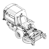
g025242
Figure12
1.PTOguardremovedfor
clarity
2.Loosenthelocknuts.
6.Raisethemowerdeck;refertoRaisingthe
MowerDeckintotheServicePosition(page17).
7.Removetheboltandwasheratthefrontofeach
FRSbafe(Figure13).
8.Rotatethebafesintothedesiredpositionand
installtheboltandwasher.
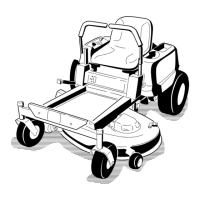
g007577
Figure13
1.Bafes—closedposition
2.Bafes—openposition
3.Bolt
4.Washer
5.Bafes
9.Lowerthemowerdeck;refertoLoweringthe
MowerDecktotheOperatingPosition(page18).
10.Slightlytightenthelocknutsontherearstuds
oftheFRSbafes.
Note:Thelocknutsontherearstudsmaybe
leftslightlylooseifyouanticipateadjustingthe
bafefrequently.
11.InstallthePTOguardusingtheclevispinsand
hairpincottersremovedinstep3.
TheSafety-Interlock
System
CAUTION
Ifthesafety-interlockswitchesare
disconnectedordamaged,themachinecould
operateunexpectedly,causingpersonal
injury.
•Donottamperwiththeinterlockswitches.
•Checktheoperationoftheinterlock
switchesdailyandreplaceanydamaged
switchesbeforeoperatingthemachine.
19

 Loading...